Sign In
Upload
Manuals
Brands
Generac Power Systems Manuals
Portable Generator
5308
Generac Power Systems 5308 Manuals
Manuals and User Guides for Generac Power Systems 5308. We have
2
Generac Power Systems 5308 manuals available for free PDF download: Diagnostic And Repair Manual, Repair Manual
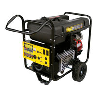
Generac Power Systems 5308 Repair Manual (90 pages)
ULTRA SOURCE PORTABLE GENERATOR
Brand:
Generac Power Systems
| Category:
Portable Generator
| Size: 15.55 MB
Table of Contents
Notice to Users of this Manual
2
Replacement Parts
2
Table of Contents
3
Table of Contents
4
Generator Fundamentals
5
Section 1: Generator Fundamentals
5
Magnetism
5
Electromagnetic Fields
5
Electromagnetic Induction
5
A SIMPLE AC Generator
6
A more Sophisticated AC Generator
6
Section 1: Generator Fundamentals
7
Measuring Electricity
8
Section 2: Measuring Electricity
8
Meters
8
The vom
8
Measuring AC Voltage
8
Measuring DC Voltage
8
Measuring AC Frequency
8
Measuring CURRENT
9
Measuring RESISTANCE
9
Section 2: Measuring Electricity
10
Electrical Units
10
OHM'S Law
10
Description and Components
11
Introduction
11
Engine-Generator Drive System
11
THE AC Generator
11
ROTOR Assembly
11
STATOR Assembly
12
Brush Holder and Brushes
12
OTHER AC Generator COMPONENTS
12
EXCITATION CIRCUIT Breaker
12
Voltage Regulator
13
Adjustment Procedure
13
CIRCUIT Breakers
14
ROTOR Residual Magnetism
14
Field Boost CIRCUIT
14
Operation
14
Startup
14
ON-Speed OPERATION
14
Field EXCITATION
14
AC Power Winding OUTPUT
14
Battery Charge Winding OUTPUT
14
10 Amp Battery Charge Winding Output
14
Insulation Resistance
15
THE Megohmmeter
15
General
15
Testing STATOR INSULATION
15
Testing ROTOR INSULATION
15
Hi-Pot Tester
15
Stator Insulation Resistance Test
15
"Testing All Stator Windings To Ground
16
TEST between Windings
16
Rotor Insulation Resistance Test
17
Cleaning the Generator
17
Drying the Generator
17
Engine DC Control System
18
Printed CIRCUIT Board
18
General
18
CIRCUIT Board CONNECTIONS
18
Dip Switch POSITIONS
18
Battery
18
Recommended Battery
18
CONTROL PANEL COMPONENT Identification
19
Terminal Block
20
OPERATIONAL Analysis
22
CIRCUIT Condition - REST
22
CIRCUIT Condition - START
24
CIRCUIT Condition - RUN
26
CIRCUIT Condition - STOP
28
FAULT Shutdown
29
Section 4: Engine DC Control System
29
Troubleshooting Flowcharts
30
Section 5: Troubleshooting Flowcharts
30
Introduction
30
IF Problem INVOLVES AC OUTPUT
30
Voltage & Frequency ARE both High or Low
30
Generator Produces ZERO Voltage or Residual Voltage (2-12 VAC)
31
EXCESSIVE Voltage/Frequency Droop When Load IS Applied
32
Problem
32
NO Battery Charge OUTPUT
33
NO 10 AMP Battery Charge OUTPUT
33
Engine will NOT CRANK
34
Engine CRANKS but will NOT START
35
Problem
35
Engine STARTS Hard and RUNS Rough
36
Engine STARTS then SHUTS down
36
Problem 10 - 10 AMP FUSE (F1) Blowing
37
Engine "HUNTS" / ERRATIC Idle
38
Section 5: Troubleshooting Flowcharts
38
Idle CONTROL "RPM Does NOT Decrease
38
Idle CONTROL "RPM Does NOT INCREASE When Load IS Applied
38
Problem 11 - UNIT Overspeeds
38
Diagnostic Tests
39
Introduction
39
Section 6: Diagnostic Tests
39
TEST 1 - CHECK NO-Load Voltage and Frequency
39
TEST 2 - CHECK MAIN CIRCUIT Breaker
39
TEST 3- TEST EXCITATION CIRCUIT Breaker
40
TEST 4 - Fixed EXCITATION TEST/ROTOR AMP Draw
40
Test 5 - Check Stepper Motor Control
42
TEST 6 - Wire Continuity
43
TEST 7 - CHECK Field Boost
43
TEST 8 - Diode/Resistor
44
Test 9 - Test Stator
45
TEST 10 - Sensing Leads
46
TEST 11 - EXCITATION Wiring
47
TEST 12 - CHECK Brush Leads
47
TEST 13 - CHECK Brushes & SLIP Rings
47
TEST 14 - CHECK ROTOR Assembly
48
TEST 15 - CHECK Load Voltage & Frequency
48
TEST 16 - CHECK Load Watts & Amperage
48
TEST 17 - CHECK Battery Charge OUTPUT
49
TEST 18 - CHECK 10 AMP Battery Charge OUTPUT
49
TEST 19 - CHECK Battery Charge RECTIFIER
49
TEST 20 - CHECK 10 AMP CIRCUIT Breaker
50
Test 21- Check 10 Amp Fuse
50
TEST 22- CHECK Battery & Cables
50
TEST 23- CHECK Voltage at STARTER CONTACTOR
51
Test 24 - Check Starter Contactor
51
Test 25 - Check Starter Motor
51
Conditions Affecting STARTER MOTOR PERFORMANCE
51
Checking the PINION
52
Tools for Starter Performance Test
52
Measuring CURRENT
52
Tachometer
52
TEST Bracket
53
Remove Starter Motor
53
Testing STARTER MOTOR
53
TEST 26 - TEST STARTER CONTACTOR Relay (SCR)
53
TEST 27- CHECK START-RUN-STOP Switch
54
TEST 28- CHECK START-RUN-STOP (Sw1) Wiring
54
TEST 29 - CHECK Ignition SPARK
55
TEST 30 - CHECK SPARK Plugs
55
TEST 31 - REMOVE Wire 18 / Shutdown Lead
56
TEST 32 - TEST START STOP Relay
56
TEST 33- TEST Wire 167
57
TEST 34 - TEST START STOP Relay Wiring
58
TEST 35 - CHECK and Adjust Ignition Magnetos
58
TEST 36: TEST FUEL SHUTOFF Solenoid
59
TEST 37: TEST FUEL SHUTOFF Solenoid Voltage
59
Test 38: Check Fuel Pump
59
TEST 39 - CHECK Carburetion
60
TEST 40 - VALVE Adjustment
60
TEST 41 - CHECK Engine / Cylinder LEAK down TEST / COMPRESSION TEST
61
TEST 42 - CHECK OIL PRESSURE Switch and Wire
62
TEST 43: CHECK START STOP Relay (SSR)
62
TEST 44: TEST STARTER CONTACTOR Relay (SCR)
63
TEST 45: CHECK Wire 15 CIRCUIT
63
TEST 46: CHECK Wire 14 CIRCUIT
63
TEST 47: CHECK FUEL SHUTOFF Solenoid
63
Test 48: Check Hourmeter
64
TEST 49: CHECK Wire 15B
64
TEST 50: CHECK Wire 167
64
TEST 51: CHECK Wires 11S & 44S
64
TEST 52: CHECK Idle CONTROL Switch (Sw2)
65
TEST 53: CHECK Idle CONTROL Wiring
65
TEST 54: CHECK Idle CONTROL TRANSFORMERS
66
TEST 55: CHECK TR1 & TR2 Wiring
66
Section 6: Diagnostic Tests
67
Test 56: Choke Test
67
Disassembly and Exploded Views
68
MAJOR Disassembly
68
Generator - Figure a
70
FRAME, Handle & Wheels - Figure B
72
Section 8: Electrical Data
74
Electrical Data
74
Wiring Diagram 12.5 & 15 Kw (UNITS Without HOURMETER) - Drawing NO. 0E0228
74
ELECTRICAL SCHEMATIC 12.5 & 15 Kw (UNITS Without HOURMETER) - Drawing NO. 0E0229-A
76
Wiring Diagram 12.5 & 15 Kw (UNITS with HOURMETER) - Drawing NO. 0D4609-D
78
ELECTRICAL SCHEMATIC 12.5 & 15 Kw (UNITS with HOURMETER) - Drawing NO. 0D6297-A
80
Section 8: Electrical Data
81
Engine Wiring
82
Wiring Diagram 17.5 Kw UNITS - Drawing NO. 0G0731
82
ELECTRICAL SCHEMATIC 17.5 Kw UNITS - Drawing NO. 0G0733
84
Wiring Diagram, 17.5 Kw MANUAL TRANSFER Switch - Drawing NO. 0G1065
85
INTERCONECTION Drawing - 17.5 Kw Generator
86
Specifications & Charts
88
Generator SPECIFICATIONS
88
Engine SPECIFICATIONS
88
Engine Speeds and Voltage SPECIFICATIONS
88
Torque SPECIFICATIONS
89
TRIM Torque SPECIFICATIONS
89
Advertisement
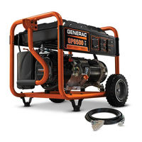
Generac Power Systems 5308 Diagnostic And Repair Manual (98 pages)
Portable Generators
Brand:
Generac Power Systems
| Category:
Portable Generator
| Size: 22.7 MB
Table of Contents
Read this Manual Thoroughly
2
Replacement Parts
2
Table of Contents
3
Section 1 Description and Components
5
Introduction
5
Engine-Generator Drive System
5
The AC Generator
5
Rotor Assembly
5
Stator Assembly
5
Brush Holder and Brushes
6
Other AC Generator Components
6
Excitation Circuit Breaker
6
Voltage Regulator
6
Adjustment Procedure (12.5 Kw and Older 15 Kw Units)
7
Adjustment Procedure (Newer 15 Kw and All 17.5 Kw Units)
7
Circuit Breakers
7
Rotor Residual Magnetism
7
Field Boost Circuit
7
Operation
8
Startup
8
On-Speed Operation
8
Field Excitation
8
AC Power Winding Output
8
Battery Charge Winding Output
8
10 Amp Battery Charge Winding Output
8
Specifications
9
Section 2 Engine DC Control System
11
Printed Circuit Board
11
General Theory
11
Circuit Board Connections
11
Dip Switch Positions
11
Battery
11
Recommended Battery
11
Control Panel Component Identification
12
Operational Analysis (Older Units)
14
Circuit Condition - Rest
14
Circuit Condition - Start
16
Circuit Condition - Run
18
Circuit Condition - Stop
20
Fault Shutdown
21
Operational Analysis (Newer Units)
22
Circuit Condition - Rest
22
Circuit Condition - Start
24
Circuit Condition - Run
26
Circuit Condition - Stop
28
Fault Shutdown
28
Section 3 Troubleshooting Flowcharts
31
Introduction
31
Section 4 AC Diagnostic Tests
39
Introduction
39
Safety
39
Important Note Concerning Connectors
39
Test 1 - Check No-Load Voltage and Frequency
39
Test 2 - Check Main Circuit Breaker
40
Test 3 - Test Excitation Circuit Breaker
40
Test 4 - Fixed Excitation Test/Rotor Amp Draw Test
40
Test 5 - Check Stepper Motor Control
42
Test 6 - Wire Continuity
43
Test 7 - Check Field Boost
44
Test 8 - Diode/Resistor
44
Test 9 - Test Stator
45
Test 10 - Sensing Leads
46
Test 11 - Excitation Wiring
47
Test 12 - Check Brush Leads
47
Test 13 - Check Brushes & Slip Rings
48
Test 14 - Check Rotor Assembly
48
Test 15 - Check Load Voltage & Frequency
49
Test 16 - Check Load Watts and Amperage
49
Test 17 - Check Battery Charge Output
49
Test 18 - Check 10 Amp Battery Charge Output
49
Test 19 - Check Battery Charge Rectifier (BCR2)
50
Test 20 - Check 10 Amp Circuit Breaker
50
Test 21 - Check 10 Amp Fuse
51
Test 22 - Check Battery and Cables
51
Test 23 - Check Voltage at Starter Contactor (SC)
52
Test 24 - Check Starter Contactor (SC)
52
Test 25 - Check Starter Motor
52
Test 26 - Test Starter Contactor Relay (SCR)
53
Test 27 - Check Start-Run-Stop Switch (SW1)
54
Test 28 - Check Start-Run-Stop Switch (SW1) Wiring
54
Test 29 - Check Ignition Spark
54
Test 30 - Check Spark Plugs
55
Test 31 - Remove Wire 18 / Shutdown Lead
55
Test 32 - Test Start Stop Relay (SSR)
55
Test 33 - Test Wire 167
56
Test 34 - Test Start Stop Relay Wiring
57
Test 35 - Check and Adjust Ignition Magnetos
58
Test 36 - Test Fuel Shutoff Solenoid (FSS)
59
Test 37 -Test Fuel Shutoff Solenoid Voltage
59
Test 38 - Check Fuel Pump
59
Test 39 - Check Carburetion
59
Test 40 - Valve Adjustment
60
Test 41 - Check Engine / Cylinder Leak down Test / Compression Test
61
Test 42 - Check Oil Pressure Switch and Wire 86
62
Test 43 - Check Start Stop Relay (SSR)
62
Test 44 - Test Starter Contactor Relay (SCR)
63
Test 45 - Check Wire 15 Circuit
63
Test 46 - Check Wire 14 Circuit
63
Test 47 - Check Fuel Shutoff Solenoid (FSS)
63
Test 48 - Check Hour Meter
64
Test 49 - Check Wire 15B
64
Test 50 - Check Wire 167
64
Test 51 - Check Wires 11S & 44S or 11S & 22S
64
Test 52 - Check Idle Control Switch (SW2)
65
Test 53 - Check Idle Control Wiring
65
Test 54 - Check Idle Control Transformers (ICT)
66
Test 55 - Check TR1 & TR2 Wiring
66
Test 56 - Choke Test
67
Insulation Resistance
67
The Megohmmeter
67
Introduction
67
Testing Stator Insulation
67
Testing Rotor Insulation
67
Hi-Pot Tester
68
Stator Insulation Resistance Test
68
Testing All Stator Windings to Ground
68
Test between Windings
69
Rotor Insulation Resistance Test
69
Cleaning the Generator
69
Drying the Generator
69
Wattage Reference Guide
70
Section 5 Disassembly
71
Major Disassembly
71
Section 6 Electrical Data
79
Introduction
79
Wiring Diagram 12.5 & 15 Kw (Units Without Hourmeter) - Drawing No. 0E0228
80
Wiring Diagram 12.5 & 15 Kw (Units Without Hourmeter) - Drawing No. 0E0228
81
Electrical Schematic 12.5 & 15 Kw (Units Without Hourmeter) - Drawing No. 0E0229-A
82
Electrical Schematic 12.5 & 15 Kw (Units Without Hourmeter) - Drawing No. 0E0229-A
83
Wiring Diagram 12.5 & 15 Kw (Units with Hourmeter) - Drawing No. 0D4609-D
84
Wiring Diagram 12.5 & 15 Kw (Units with Hourmeter) - Drawing No. 0D4609-D
85
Electrical Schematic 12.5 & 15 Kw (Units with Hourmeter) - Drawing No. 0D6297-A
86
Electrical Schematic 12.5 & 15 Kw (Units with Hourmeter) - Drawing No. 0D6297-A
87
Wiring Diagram 17.5 Kw - Drawing No. 0G0731
88
Wiring Diagram 17.5 Kw - Drawing No. 0G0731
89
Electrical Schematic 17.5 Kw - Drawing No. 0G0733
90
Electrical Schematic 17.5 Kw - Drawing No. 0H0729
91
Wiring Diagram 17.5 Kw - Drawing No. 0H0730
92
Wiring Diagram 17.5 Kw - Drawing No. 0H0730
93
Wiring Diagram, 17.5 Kw Manual Transfer Switch - Drawing No. 0G1065
94
Interconnection Drawing - 17.5 Kw Generator Connected to the External Connection Box, Manual Transfer Switch and Home's Main Electrical Distribution Panel
95
Advertisement
Related Products
Generac Power Systems 5500EXL
Generac Power Systems 5500XL
Generac Power Systems 5681
Generac Power Systems 5606
Generac Power Systems 5622
Generac Power Systems PowerBOSS 5500 Storm-Plus
Generac Power Systems WHEELHOUSE 5550 1646-3
Generac Power Systems 5.6 kVA PowerPact
Generac Power Systems 5734
Generac Power Systems 5847
Generac Power Systems Categories
Portable Generator
Inverter
Pressure Washer
Switch
Lighting Equipment
More Generac Power Systems Manuals
Login
Sign In
OR
Sign in with Facebook
Sign in with Google
Upload manual
Upload from disk
Upload from URL