Sign In
Upload
Manuals
Brands
GEA Manuals
Control Systems
T.VIS M-15
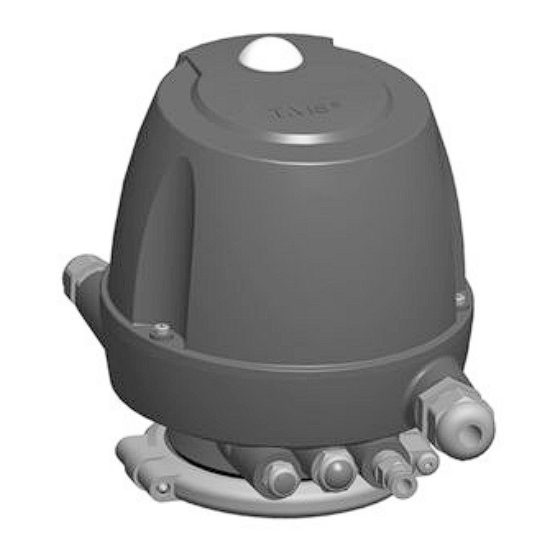
GEA T.VIS M-15 Position Controller Manuals
Manuals and User Guides for GEA T.VIS M-15 Position Controller. We have
2
GEA T.VIS M-15 Position Controller manuals available for free PDF download: Operating Instructions Manual, Operating Instruction
GEA T.VIS M-15 Operating Instructions Manual (130 pages)
Brand:
GEA
| Category:
Industrial Equipment
| Size: 6 MB
Table of Contents
Table of Contents
3
Notes for the Reader
6
Binding Character of These Operating Instructions
6
Notes on the Illustrations
6
Symbols and Highlighting
7
Abbreviations and Terms
8
Safety
10
Safety Note
10
Operator's Duties
10
Qualification of Staff
11
Supplementary Regulations
12
Instructions for the Safe Operation
13
General Principles
13
Installation
13
Commissioning/Setup Mode
14
Setting into Operation
14
Operation
14
Shutting down
15
Maintenance and Repair
15
Disassembly
16
Environmental Protection
16
Electrical Equipment
16
Signage
17
Residual Risk
17
Hazard Areas
17
Residual Dangers
18
Electrostatically Endangered Components and Modules
18
Transport and Storage
19
Scope of Supply
19
Transport
19
Storage
19
Intended Purpose
20
Designated Use
20
Requirements for the Operation
20
Improper Operating Conditions
21
Conversion Work
21
IP Protection Classes
22
Design and Function
23
Design
23
Function
26
Operation Principle
26
Control Top Without Solenoid Valves
26
Control Top with Solenoid Valves
27
Control Top with Cap
27
Safety Air Exhaust/Installation Position
28
Connection
29
Establishing Hose Connections
29
Pneumatic Connections
29
Control Top Without or with 1 Solenoid Valve
29
Control Top with 2 Solenoid Valves
30
Control Top with 3 Solenoid Valves
31
Electrical Connections
32
Overview
32
ASI Connections
33
External Proximity Switch (170)
35
Electrical 24 V DC Wiring
36
Electrical Wiring of AS-Interface V.3.0
39
Electrical Wiring of AC-Interface - AC Voltage
40
Electrical Devicenet Wiring
41
Wiring Diagram for 24 V DC Control Systems with P Logic
43
Wiring Diagram for 24 V DC Control Systems with N Logic
45
Wiring Diagram for T.VIS M-15 with Adapter Module
47
Wiring Diagram for T.VIS M-15 24 V DC
48
Visual Display
49
Setting into Operation
50
Switching on the Control Air
50
Switching on the Operating Voltage
50
Checking Valve Actuation
51
Service Function
51
Adjusting the Sensor in the Control Top
52
Seat Valves - Position of Sensor S1 down
52
Seat Valves - Position of Sensor S1 up
56
T-Smart Butterfly Valves
59
Adjusting the Proximity Switch in the Lantern on Double-Disks Without Balancer
62
Adjusting the Proximity Switch in the Lantern of PMO Valve Type M/2.0
64
Test Procedure for Tuchenhagen PMO Valves Type M/2.0
67
Purpose
67
Process Overview
67
Hardware Description
67
Test Procedure 1
68
Test Procedure 2
69
Mounting the Control Top to Different Valves
70
Mounting to VARIVENT Valve or STERICOM Valve Types N_A/D, R
71
Mounting to a Butterfly Valve T-Smart 8000
72
Mounting to a Butterfly Valve T-Smart 7 and a Mixproof Butterfly Valve T-Smart 9
73
Mounting to ECOVENT Valves N_ECO and W_ECO
74
Mounting to VESTA Valve H_A/M
76
Mounting to VESTA Valve H_A
78
Mounting to Valve N_/E or W_/E or STERICOM Valve
80
Mounting to a T-Smart Single-Seat and Double-Seal Valve
81
Fitting to an ASEPTOMAG Valve
83
Replacing Control Tops
84
Malfunctions
85
Maintenance
86
Inspections
86
Cleaning
87
Removing the Control Top from the Valve
87
Dismantling the Control Top into Its Components
88
Variants of the Control Top
88
Removing the Cap
89
Removing the Solenoid Valves and the Control Plate
90
Removing the Logic Element NOT (Sealing Package)
92
Fitting the Logic Element NOT (Sealing Package)
93
Removing the Adapter Module
94
Removing the Interface Module
95
Removing the Pneumatic Block
96
Fitting the Pneumatic Block
97
Replacing the Seals on the Base
98
Disposal
99
Technical Data
100
Type Plate
100
General Technical Data
102
Specification of 24 V DC Interface Module
104
Specifications for AS-Interface Adapter Module
105
Specifications for Devicenet Adapter Module
106
DIP Switch
107
Specifications for AC-Interface Adapter Module
108
Accessories
109
Tools
109
Lubricants
110
Equipment
110
Spare Parts List
112
Dimension Sheet
123
Spare Parts Lists - Switch Bar
124
Dimension Sheet - Switch Bar
126
Advertisement
GEA T.VIS M-15 Operating Instruction (120 pages)
Control and feedback systems
Brand:
GEA
| Category:
Control Systems
| Size: 11 MB
Table of Contents
Test Procedure
2
Table of Contents
3
General Information
7
Information on the Document
7
Binding Character of These Operating Instructions
7
Notes on the Illustrations
7
Symbols and Highlighting
7
Manufacturer Address
8
Contact
8
Safety
9
Intended Use
9
Requirements for Operation
9
Improper Operating Conditions
9
Operator's Duty of Care
10
Subsequent Changes
10
IP Protection Classes
11
General Safety Instructions and Dangers
11
Principles for Safe Operation
12
Environmental Protection
12
Electrical Equipment
12
Supplementary Regulations
13
Qualification of Personnel
13
Safety Equipment
14
Signs
14
Residual Dangers
15
Electrostatically Endangered Components and Modules
15
Danger Zones
16
Description
17
Design
17
Functional Description
19
Operation Principle
19
Control Top Without Solenoid Valves
19
Control Top with Solenoid Valves
20
Control Top with Cap
20
Safety Air Exhaust/Installation Position
20
Transport and Storage
22
Storage Conditions
22
Transport
22
Scope of Supply
22
Technical Data
23
Type Plate
23
Technical Data
26
Specifications Interface Module 24V DC Version
28
Specifications for AS-Interface Adapter Module
29
Specifications for Devicenet Adapter Module
30
DIP Switch
31
Accessories
32
Tool
33
Lubricants
34
Equipment
34
Assembly and Installation
36
Safety Instructions
36
Establishing Hose Connections
36
Pneumatic Connections
36
Control Top with 1 Solenoid Valve or Without Solenoid Valve
37
Control Top with 2 Solenoid Valves
38
Control Top with 3 Solenoid Valves
39
Electrical Connections
40
Overview
40
ASI Connections
41
External Proximity Switch
42
Electrical 24 V DC Wiring
42
Plug M12 / 5-Pin (24.5)
43
Plug M12 / 8-Pin (24.1)
43
6.4.4.3 Interface Module with 2 Sensors
44
Electrical Wiring of AS-Interface
46
Plug M12 / 2-Pin (24.3)
46
Electrical Devicenet Wiring
47
Plug M12 / 5-Pin (24.2)
47
6.4.6.2 Devicenet Adapter Module
48
Wiring Diagram for 24 V DC Control Systems with P Logic
49
Wiring Diagram for 24 V DC Control Systems with N Logic
51
Wiring Diagram for T.VIS M-15 with Adapter Module
52
Wiring Diagram for T.VIS M-15 24 V DC
54
Visual Display
56
Illuminated Dome
56
Mounting the Control Top to Different Valves
56
Mounting to VARIVENT Valve or STERICOM Valve Types N_A/D, R
58
Mounting to a Butterfly Valve T-Smart 8000
59
Mounting to a Butterfly Valve T-Smart 7 and a Mixproof Butterfly Valve T-Smart 9
61
Mounting to ECOVENT Valves N_ECO and W_ECO
62
Mounting to VESTA Valve H_A/M
64
Mounting to VESTA Valve H_A
66
Mounting to Valve N_/E or W_/E or STERICOM Valve
68
Mounting to a T-Smart Single-Seat and Double-Seal Valve
70
Fitting to an ASEPTOMAG Valve
71
Replacing Control Tops
72
Start-Up
73
Safety Notes
73
Checking Valve Actuation
74
Service Function
74
Adjusting the Sensor in the Control Top
74
Seat Valves - Position of Sensor S1 up
77
T-Smart Butterfly Valves
79
Adjust the Proximity Switch in the Lantern - for Unbalanced Double Disks of the Valves D, R, Y, B, T_R
82
Adjusting the Proximity Switch in the Lantern of PMO Valve Type M/2.0
84
Test Procedure for Tuchenhagen PMO Valves Type M
86
Purpose
87
Process Overview
87
Hardware Description
87
Test Procedure 1
87
Operation and Control
90
Safety Instructions
90
Cleaning
91
Maintenance
92
Safety Instructions
92
Inspections
93
Removing the Control Top from the Valve
94
Dismantling the Control Top into Its Components
95
Variants of the Control Top
95
Removing the Cap
95
Removing the Solenoid Valves and the Control Plate
96
Removing the Logic Element NOT (Seal Pack)
97
Fitting the Logic Element NOT (Sealing Package)
98
Removing the Adapter Module
99
Removing the Interface Module
99
Removing the Pneumatic Block
100
Fitting the Pneumatic Block
100
10.4.10 Install Pneumatic Connections
102
Maintenance
102
Replacing the Seals on the Base
102
Alarms
104
Malfunctions and Remedies
104
Decommissioning
105
Safety Instructions
105
Disposal
105
General Notes
105
Spare Parts List - Control Top Type T.VIS
106
Spare Parts List - Switch Bar T.VIS
111
Dimension Sheet - Control Top Type T.VIS
113
Dimension Sheet - Switch Bar LFT-R T.VIS M-15 for Lifted Valves
114
Appendix
117
Lists
117
Abbreviations and Terms
117
Advertisement
Related Products
GEA T.VIS M-20 FDD
GEA T.VIS P-15
GEA T.VIS E-20
GEA T.VIS A-15
GEA VARICOVER MST 3A
GEA T.VIS M-20
GEA MAXA L
GEA T.VIS P-1
GEA T.VIS Q-15
GEA D 10
GEA Categories
Control Unit
Air Compressor
Water Pump
Compressor
Industrial Equipment
More GEA Manuals
Login
Sign In
OR
Sign in with Facebook
Sign in with Google
Upload manual
Upload from disk
Upload from URL