
Related Manuals for GEA T.VIS M-15


Summary of Contents for GEA T.VIS M-15
- Page 1 Control and feedback systems ® GEA T.VIS M-15 Operating instruction (Translation from the original language) 430BAL010697EN_2...
-
Page 2: Test Procedure
EU Machinery Directive. This document is protected by copyright. All rights reserved. The document may not, in whole or in part, be copied, reproduced, translated or reduced to an electronic medium of machine-readable form without the express permission of GEA Tuchenhagen GmbH. LEGAL NOTICE Word marks ®... -
Page 3: Table Of Contents
TABLE OF CONTENTS General Information Information on the Document 1.1.1 Binding Character of These Operating Instructions 1.1.2 Notes on the Illustrations 1.1.3 Symbols and Highlighting Manufacturer address Contact Safety Intended use 2.1.1 Requirements for operation 2.1.2 Improper operating conditions Operator’s Duty of Care Subsequent changes IP Protection Classes General safety instructions and dangers... - Page 4 Wiring Diagram for 24 V DC Control Systems with P Logic 6.4.8 Wiring Diagram for 24 V DC Control Systems with N Logic 6.4.9 Wiring Diagram for T.VIS M-15 with Adapter Module 6.4.10 Wiring Diagram for T.VIS M-15 24 V DC Visual Display 6.5.1...
- Page 5 General notes Spare parts list - control top type T.VIS M-15 Spare parts list - Switch bar T.VIS M-15 Dimension sheet - Control top type T.VIS M-15 Dimension sheet - Switch bar LFT-R T.VIS M-15 for lifted valves Appendix 17.1 Lists 17.1.1...
- Page 6 430BAL010697EN_2 15.04.2020...
-
Page 7: General Information
General Information Information on the Document General Information Information on the Document The present Operating Instructions are part of the user information for the product. The Operating Instructions contain all the information you need to transport, install, commission, operate and carry out maintenance for the product. 1.1.1 Binding Character of These Operating Instructions These Operating Instructions contain the manufacturer's instructions to the... -
Page 8: Manufacturer Address
Second step in a sequence of operations. ® Result of the previous operation. ® The operation is complete, the goal has been achieved. Hint! Further useful information. Manufacturer address GEA Tuchenhagen GmbH Am Industriepark 2-10 21514 Büchen Contact Tel.:+49 4155 49-0 Fax:+49 4155 49-2035 flowcomponents@gea.com www.gea.com 430BAL010697EN_2 15.04.2020... -
Page 9: Safety
In addition, with T.VIS M-15 you can monitor the non-actuated position of the double-disk with an initiator in the lantern for all double-seat valves. The control top T.VIS M-15 may not be used in areas where ATEX approval is required. -
Page 10: Operator's Duty Of Care
Safety Operator’s Duty of Care • Safety devices are not working or were removed. • Malfunctions have been detected on the component. • Damage to the component has been detected. • Maintenance intervals have been exceeded. Operator’s Duty of Care The operating company of the component has a special responsibility for the proper and safe handling of the component within their company. -
Page 11: Ip Protection Classes
This ensures that the component is always operating properly and efficiently. IP Protection Classes The control top T.VIS M-15 in its standard version fulfils the requirements of protection class IP66 (DIN EN 60529). Models in protection classes IP67 or IP69k (both DIN EN 60529) are also available. -
Page 12: Principles For Safe Operation
Safety General safety instructions and dangers • the component is not used as intended • the component is used improperly • the component is operated under impermissible conditions 2.5.1 Principles for safe operation Dangerous situations during operation can be avoided by safety-conscious and proactive behaviour of the staff. -
Page 13: Supplementary Regulations
Safety Supplementary Regulations • After completion of all work, check that the protective devices are fully functional. Supplementary Regulations In addition to the instructions in this documentation the following also has to be observed: • pertinent accident prevention regulations, • generally accepted safety rules, •... -
Page 14: Safety Equipment
Safety Safety equipment When working with the component, a distinction is made between the following user groups: User groups Staff Qualifications Operating personnel Adequate instruction and sound knowledge in the following areas: • Functionality of the component • Operating sequences on the pump •... -
Page 15: Residual Dangers
• be careful not to touch the electronic components, • also take care not to touch electronic components when supply voltage is present. Use ESD-compliant packaging when returning electronic components. (Contact GEA Tuchenhagen if you have any questions.) 430BAL010697EN_2 15.04.2020... -
Page 16: Danger Zones
Safety Danger zones 2.10 Danger zones Please observe the following notes: • In the event of malfunctions, shut down the control top (disconnect from the power and air supply) and secure it against being used. • Before starting any service, maintenance or repair work, disconnect the control top from the power supply and secure it against inadvertently being switched back on again. -
Page 17: Description
Logic element NOT, optional 21.1 Throttle, optional Control plate/blind plate External proximity switch, Cable gland optional The T.VIS M-15 control top consists of: • a 24 VDC interface module with 2 sensors for the detection of the two valve end positions, 430BAL010697EN_2 15.04.2020... - Page 18 Description Design • an additional adapter module for the interface modules AS-Interface, DeviceNet (optional), • a maximum of three solenoid valves for the actuation of the main stroke and the lift strokes, • a logic element NOT (optional) for backup of the valve's main spring or for the actuation of indifferent actuators (air/air), •...
-
Page 19: Functional Description
3.2.2 Control Top without Solenoid Valves The control top T.VIS M-15 without solenoid valves works as a position indicator. Once the two sensors have been adjusted, the control top indicates the status of the process valve locally by coloured LEDs under the illuminated dome so that it is visible over a long distance. -
Page 20: Control Top With Solenoid Valves
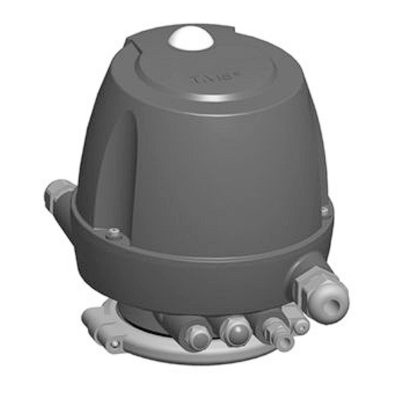
Description Functional description To adjust the second sensor, the process valve must be moved once to its end positions by an external solenoid valve. 3.2.3 Control Top with Solenoid Valves The control top with solenoid valves acts as a control top. The signalling takes place in the same way as with the control top without solenoid valves. - Page 21 Description In operating mode, the exhaust air from the lifting actuators is discharged via this vent plug. In the unlikely event of a damaged solenoid valve or in case of sealing problems, pressure relief is ensured. Fig.7: Control Top with Cap This vent plug is a safety device that must be handled as such.
-
Page 22: Transport And Storage
Transport and storage Storage conditions Transport and storage Storage conditions You must first dry and preserve the control top to prevent damage if the control top is exposed to temperatures ≤ 0°C during transport or storage. Hint! We recommend that the valve should be stored at a temperature of ≥ 5 °C for a period of 24 hours prior to any handling (disassembling the housings / activation of actuators) so that any ice crystals formed by condensation water can melt. -
Page 23: Technical Data
Explanation of the items in the order code Item in the order code Designation Explanation Feedback location T M 1 5 Control Top T.VIS M-15 Control top type without solenoid valve 1 solenoid valve Y1 1 solenoid valve Y1 (retrofittable: Y2, Y3) - Page 24 Technical data Type plate Explanation of the items in the order code Item in the order code Designation Explanation 3 solenoid valves Y1, Y2, 1 solenoid valve Y1 (retrofittable: Y2, Y3) 1 NOT element 2 solenoid valves Y1, Y2, (retrofittable: Y3) 1 NOT element 3 solenoid valves Y1, Y2, 1 logic element NOT...
- Page 25 Technical data Type plate Explanation of the items in the order code Item in the order code Designation Explanation Air connection metric, 8- pin connector M12 (>1 solenoid valve, >2 feedback signals) Air connection Inch, 8-pin connector M12 (>1 solenoid valve, >2 feedback signals) Air connection metric, 5- pin connector M12...
-
Page 26: Technical Data
Technical data Technical data Explanation of the items in the order code Item in the order code Designation Explanation 5-pin M12 junction box for screw connection J, P (Material No. 508-963) 8-pin M12 junction box for screw connection H, I (Material No. 508-061) Protection class IP 67 (immersion) - Page 27 Technical data Technical data Technical data: Temperatures and compressed air supply Designation Description - Water content: Quality class 4 max. dew point +3 °C If the unit is used at higher altitudes or at low ambient temperatures, the dew point must be adapted accordingly. - Oil content: Quality class 3 preferably oil free,...
-
Page 28: Specifications Interface Module 24V Dc Version
Technical data Specifications interface module 24V DC Version Technical data: Electrical information Designation Description EC Low Voltage Directive 73/23/EEC Electrical wiring configuration – 5-pin M12 circular connector or – 8-pin M12 circular connector only for 24 V version with 2 to 3 solenoid valves –... -
Page 29: Specifications For As-Interface Adapter Module
Technical data Specifications for AS-Interface Adapter Module Technical data: inputs for solenoid valve activation Designation Description Control voltage max. 24 V DC (+20 % / -12.5 %) Current consumption, solenoid valve 35 mA Technical data: Outputs Designation Description Maximum power rating per feedback 50 mA output Voltage drop at the outputs... -
Page 30: Specifications For Devicenet Adapter Module
Technical data Specifications for DeviceNet Adapter Module Technical data: inputs (I/O matrix) Feedback Input 1“Start” Input 2 “End” Input 3 “Main stroke Y3” Not used Technical data: Outputs (I/O matrix) Actuation Activation of solenoid valve Y1 Activation of solenoid valve Y2 Activation of solenoid valve Y3 Reserved for A/B identification Technical data: Design of I/O module for T.VIS... -
Page 31: Dip Switch
Technical data DIP Switch Technical data: power supply Designation Description EDS file F1022_R4.eds *Observe the operating current for the 24 V DC interface module! Technical data: inputs (I/O matrix) Feedback Input 1“Start” Input 2 “End” Input 3 “Main stroke Y3” Technical data: Outputs (I/O matrix) Actuation Activation of solenoid valve Y1... -
Page 32: Accessories
Technical data Accessories Switches 1 and 2 = baud rate DIP 1 DIP 2 Baud rate 125 kBaud 250 kBaud 500 kBaud Selectable via software Delivery state Fig.10: DIP switch: Switches 3 and 8 = MAC ID (address) Switches 3 to 8 = MAC ID (address) DIP 3 DIP 4 DIP 5... -
Page 33: Tool
Technical data Tool Fig.11 Accessories Part no. Cable socket (101), angular – M12; 5-pin: A-coded 508-963 Cable socket (101), straight – M12; 8-pin: A-coded 508-061 Cable socket (101), straight – M12; with 1 m cable and ASI 508-027 insulation displacement connector Cable socket (101), straight –... -
Page 34: Lubricants
Technical data Lubricants List of tools Tool Material no. Screw driver Torx 10 IP Screw driver Torx 20 IP Plus Crosstip screwdriver size 2 Slotted screw driver A 0.4 x 2.5 Flat-nose pliers Pin punch/mandrel Ø6.0 mm Lubricants Lubricants Material no. Rivolta F.L.G. - Page 35 Technical data Technical data - equipment Equipment Material no. Sound absorber G 1/8" • Filter material: stainless steel wool 933-175 • Ambient temperature: -20...+70 °C • max. pressure 10 bar Sound absorber G 1/4" • Filter material: stainless steel wool 933-174 •...
-
Page 36: Assembly And Installation
Assembly and installation Safety instructions Assembly and installation Safety instructions Hazardous situations during installation can be avoided by safety-conscious and proactive behaviour of the personnel. For installation, the following principles apply: • Only qualified personnel are allowed to set-up, install and commission the component. -
Page 37: Control Top With 1 Solenoid Valve Or Without Solenoid Valve
Before removing a sealing plug (23), make sure that the respective air connection is pressure-free! On most of the GEA Tuchenhagen valve types, solenoid valve Y1 internally guides the main control air through the switch bar into the main actuator. The external air connection Y1 is provided in addition. -
Page 38: Control Top With 2 Solenoid Valves
Before removing a sealing plug (23), make sure that the respective air connection is pressure-free! On most of the GEA Tuchenhagen valve types, solenoid valve Y1 internally guides the main control air through the switch bar into the main actuator. The external air connection Y1 is provided in addition. -
Page 39: Control Top With 3 Solenoid Valves
Before removing a sealing plug (23), make sure that the respective air connection is pressure-free! On most of the GEA Tuchenhagen valve types, solenoid valve Y1 internally guides the main control air through the switch bar into the main actuator. The external air connection Y1 is provided in addition. -
Page 40: Electrical Connections
Assembly and installation Electrical connections Electrical connections Danger To satisfy the UL requirements, use a protective insulation power-limited power supply according to UL/IEC 60950 or power limited according to UL/IEC 61010-1 3cd cl. 9.4 or a Class II power supply according to NEC. ►... -
Page 41: Asi Connections
Assembly and installation Electrical connections 6.4.2 ASI Connections ASI BOX connection (24.4) Carry out the following steps: Open the terminal box. Insert the flat cable (4) into the insulation displacement connector (3). Close the terminal box. The electrical contact is established by pressing on the upper part. -
Page 42: External Proximity Switch
Assembly and installation Electrical connections • Done Connector (24.3) M12/5-pin for DeviceNet Carry out the following steps: ® Connect the DeviceNet cable using plug-in connection M12/5-pin. • Done Connector (24.1/24.5) M12/5-pin and M12/8-pin for 24V DC Carry out the following steps: ®... -
Page 43: Plug M12 / 5-Pin (24.5)
Assembly and installation Electrical connections 6.4.4.1 Plug M12 / 5-pin (24.5) Fig.18: 5-pin M12 connector A-coded: device connector and view of male connector Corresponding cable socket part no. 508-963. L+24 V DC supply voltage Feedback of end position L- reference potential Feedback of non-actuated position Actuation of solenoid valve Y1 Carry out the following steps:... -
Page 44: 6.4.4.3 Interface Module With 2 Sensors
Assembly and installation Electrical connections Corresponding cable socket part no. 508-061, see Chapter 13, Page 106. L+24V DC supply voltage Feedback of end position L- reference potential Feedback of non-actuated position Actuation of solenoid valve Y1 Actuation of solenoid valve Y2 Actuation of solenoid valve Y3 Feedback (external proximity switch) Carry out the following steps:... - Page 45 * The feedback signal for the non-actuated position of the double-disk to the PLC is temporarily or permanently interrupted when the valve stroke is activated (valve-specific). GEA Tuchenhagen recommends ignoring the feedback signal from the external proximity switch in the PLC during the main stroke.
-
Page 46: Electrical Wiring Of As-Interface
Assembly and installation Electrical connections 6.4.5 Electrical Wiring of AS-Interface 6.4.5.1 Plug M12 / 2-pin (24.3) Fig.21 Matching cable sockets part nos. 508-963, 508-027 and 508-028. Connector M12/4-pole ASI+ ASI- Fig.22 Description of the function of the terminals Terminal Designation Functional description Communication and + ASI... -
Page 47: Electrical Devicenet Wiring
Assembly and installation Electrical connections Indication: flashing – peripheral equipment fault • Colour: red / yellow Indication: flashing – no data exchange / address 0 • Colour: red / green Indication: flashing – peripheral equipment fault Carry out the following steps: Connect cable via air connector M12/2-pole. -
Page 48: 6.4.6.2 Devicenet Adapter Module
Assembly and installation Electrical connections 6.4.6.2 DeviceNet adapter module Fig.24: DeviceNet adapter module: Material no. 221-589.22, see Chapter 13, Page 106 Description of the function of the terminals Terminal Designation Functional description CAN_H Communication CAN_L Communication Supply + Supply - Light-emitting diode (LED) •... -
Page 49: Wiring Diagram For 24 V Dc Control Systems With P Logic
Assembly and installation Electrical connections 6.4.7 Wiring Diagram for 24 V DC Control Systems with P Logic Fig.25 430BAL010697EN_2 15.04.2020... - Page 50 Assembly and installation Electrical connections Key to wiring diagram for 24 V DC control systems with P logic Position Description Interface module T.VIS M-15 WD.1 Type 24 V DC (material no.: 221-589.53) WD.2 Proximity switch fitted to lantern T.VIS outputs (PNP-current supplying) WD.3...
-
Page 51: Wiring Diagram For 24 V Dc Control Systems With N Logic
Assembly and installation Electrical connections 6.4.8 Wiring Diagram for 24 V DC Control Systems with N Logic Fig.26 430BAL010697EN_2 15.04.2020... -
Page 52: Wiring Diagram For T.vis M-15 With Adapter Module
17 and 18 must be removed. The separate reference potential is then applied to terminal 17. 6.4.9 Wiring Diagram for T.VIS M-15 with Adapter Module Check the assignment of the wires before connecting the cables! 430BAL010697EN_2... - Page 53 Assembly and installation Electrical connections Fig.27 430BAL010697EN_2 15.04.2020...
-
Page 54: Wiring Diagram For T.vis M-15 24 V Dc
Assembly and installation Electrical connections 6.4.10 Wiring Diagram for T.VIS M-15 24 V DC Check the assignment of the wires before connecting the cables! 430BAL010697EN_2 15.04.2020... - Page 55 Assembly and installation Electrical connections Fig.28 430BAL010697EN_2 15.04.2020...
-
Page 56: Visual Display
Assembly and installation Visual Display Visual Display 6.5.1 Illuminated dome Fig.29 Position Description Illuminated dome The following statuses are visualized by the illuminated dome: • Valve in non-actuated position: green • Valve in actuated position: yellow • Valve in a position that deviates from its adjusted actuated positions: flashing yellow •... - Page 57 Assembly and installation Mounting the Control Top to Different Valves Notice Magnetic fields can affect the proximity switch system. Measured values can be changed. ► Protect the control top from external magnetic fields. Notice The vent plug E2 is a safety element. If the element is not installed correctly or if the vent is covered, the safety function is no longer guaranteed.
-
Page 58: Mounting To Varivent Valve Or Stericom Valve Types N_A/D, R
Assembly and installation Mounting the Control Top to Different Valves 6.6.1 Mounting to VARIVENT Valve or STERICOM Valve Types N_A/D, R Fig.30 Notice The permanent magnet on the switch bar is fragile. Damage to the permanent magnet. ► Protect the permanent magnet against impact stress. Notice Magnetic fields resulting from the permanent magnet on the switch bar. -
Page 59: Mounting To A Butterfly Valve T-Smart 8000
Assembly and installation Mounting the Control Top to Different Valves 6.6.2 Mounting to a Butterfly Valve T-smart 8000 Requirement: • Pay attention not to kink the air hoses when mounting the control top. Notice The permanent magnet on the switch bar is fragile. Damage to the permanent magnet. - Page 60 Mounting the Control Top to Different Valves Close the air connection Y1 with a sealing plug (23) since the control top T.VIS M-15 has an inner air duct. Fig.32 Perform commissioning, see Chapter 6, Page 36 and Chapter 7, Page 73.
-
Page 61: Mounting To A Butterfly Valve T-Smart 7 And A Mixproof Butterfly Valve T-Smart 9
Assembly and installation Mounting the Control Top to Different Valves 6.6.3 Mounting to a Butterfly Valve T-smart 7 and a Mixproof Butterfly Valve T-smart 9 Requirement: • Pay attention not to kink the air hoses when mounting the control top. Notice The permanent magnet on the switch bar is fragile. -
Page 62: Mounting To Ecovent Valves N_Eco And W_Eco
Assembly and installation Mounting the Control Top to Different Valves 6.6.4 Mounting to ECOVENT Valves N_ECO and W_ECO Requirement: • Pay attention not to kink the air hoses when mounting the control top. Notice The permanent magnet on the switch bar is fragile. Damage to the permanent magnet. - Page 63 Assembly and installation Mounting the Control Top to Different Valves ! As the air is guided inside the T.VIS control module (B), connection A.4.2 on the actuator is closed. Carry out commissioning, see chapter “Commissioning". ® Done. 430BAL010697EN_2 15.04.2020...
-
Page 64: Mounting To Vesta Valve H_A/M
Assembly and installation Mounting the Control Top to Different Valves 6.6.5 Mounting to VESTA Valve H_A/M Requirement: • Pay attention not to kink the air hoses when mounting the control top. Notice The permanent magnet on the switch bar is fragile. Damage to the permanent magnet. - Page 65 Assembly and installation Mounting the Control Top to Different Valves As internal air guiding is not possible on VESTA valves, connect the air connection (Y1) on the control top to connection A4.2 on the actuator with an air hose (L). Perform commissioning, see Chapter 6, Page 36 and Chapter 7, Page 73.
-
Page 66: Mounting To Vesta Valve H_A
Assembly and installation Mounting the Control Top to Different Valves 6.6.6 Mounting to VESTA Valve H_A Requirement: • Pay attention not to kink the air hoses when mounting the control top. Notice The permanent magnet on the switch bar is fragile. Damage to the permanent magnet. - Page 67 Assembly and installation Mounting the Control Top to Different Valves Screw the switch bar (1) into the adapter (139) and tighten using an a/f 13 open end spanner; torque 2 Nm (1.4 lbft). Fit the control top (B) over the switch bar (1) and on the actuator. Tighten the clamps (15) and screws (39) to a torque of 1 Nm (0.7 lbft).
-
Page 68: Mounting To Valve N_/E Or W_/E Or Stericom Valve
Assembly and installation Mounting the Control Top to Different Valves 6.6.7 Mounting to Valve N_/E or W_/E or STERICOM Valve Requirement: • Pay attention not to kink the air hoses when mounting the control top. Notice The permanent magnet on the switch bar is fragile. Damage to the permanent magnet. - Page 69 Assembly and installation Mounting the Control Top to Different Valves ! As internal air guiding is not possible on these valve types, connect the air connection (Y1) on the control top to connection (A.4.2) on the actuator with an air hose (L). Perform commissioning, see Chapter 6, Page 36 and Chapter 7, Page 73.
-
Page 70: Mounting To A T-Smart Single-Seat And Double-Seal Valve
Assembly and installation Mounting the Control Top to Different Valves 6.6.8 Mounting to a T-smart Single-Seat and Double-Seal Valve Fig.39 Requirement: • Pay attention not to kink the air hoses when mounting the control top. Notice The permanent magnet on the switch bar is fragile. Damage to the permanent magnet. -
Page 71: Fitting To An Aseptomag Valve
Assembly and installation Mounting the Control Top to Different Valves 6.6.9 Fitting to an ASEPTOMAG Valve Requirement: • Pay attention not to kink the air hoses when mounting the control top. Notice The permanent magnet on the switch bar is fragile. Damage to the permanent magnet. -
Page 72: Replacing Control Tops
When a valve is used with the wrong type of switch bar, there is a risk of injury as the spring tension can suddenly be released. ► When replacing a predecessor model with a control top T.VIS M-15 the switch bar must always be replaced! 430BAL010697EN_2 15.04.2020... -
Page 73: Start-Up
Start-up Safety notes Start-up Safety notes Initial commissioning For initial commissioning, the following principles apply: • Take protective measures against dangerous contact voltages in accordance with pertinent regulations. • The control top must be completely assembled and correctly adjusted. All screw connections must be securely tightened. -
Page 74: Checking Valve Actuation
If maintenance must be conducted on a process valve that is fitted with a control top T.VIS M-15, the valve core must be pulled out of the housing. For this purpose, the valve disk pretension of the process valve must be relieved by actuating the main actuator. - Page 75 Start-up Adjusting the Sensor in the Control Top – VARIVENT, ECOVENT, STERICOM valve; except valve type U for actuator selection "Z": non-actuated position of the valve is spring-closing – VARIVENT valve type U for actuator selection "A": non-actuated position of the valve is spring-opening –...
- Page 76 Start-up Adjusting the Sensor in the Control Top Setting the switchpoint Hint! Turning the adjusting screw (1) clockwise moves the sensor upwards, turning counter-clockwise moves the sensor downwards! Carry out the following steps: Moving the switchpoint upwards ® All a/m valves except for VESTA valves: 1 turn in clockwise direction ®...
-
Page 77: Seat Valves - Position Of Sensor S1 Up
Start-up Adjusting the Sensor in the Control Top ® VESTA valves: 0.5 turns in counter-clockwise direction ® Light-emitting diode B at the interface module lights up yellow. Tighten the locking screw (2), torque 1 Nm (0.7 lbft). Cancel the actuation of solenoid valve Y1. ®... - Page 78 Start-up Adjusting the Sensor in the Control Top Caution! ► When actuating the valve for adjusting the sensor or for checking the switching function, make sure that no media are inside the valve. Caution! ► There is the risk of over-tightening the pin screw (1) ! Therefore only turn the pin screw (1) with a torque of max.
-
Page 79: T-Smart Butterfly Valves
Start-up Adjusting the Sensor in the Control Top Fig.47 Carry out the following steps: Release the locking screw (2). Turn the adjusting screw (1) of sensor S2 until light-emitting diode B at the interface module lights up yellow. Move the sensor with the adjusting screw (1) in the direction of the lower switching edge (4) of the switching range (3) until LED B flashes yellow. - Page 80 Start-up Adjusting the Sensor in the Control Top Adjusting the start position of the valve cap – valve not actuated, position of sensor S1 top Fig.48 Fig.49 Adjusting the start position; control top shown without pneumatic block Caution! ► When actuating the valve for adjusting the sensor or for checking the switching function, make sure that no media are inside the valve.
- Page 81 Start-up Adjusting the Sensor in the Control Top Hint! Turning the adjusting screw (1) clockwise moves the sensor upwards, turning counter-clockwise moves the sensor downwards! Adjusting the end position of the valve cap – main stroke of valve actuated position of sensor S2 bottom Move the valve disk to the end position either by electrical or manual actuation of solenoid valve Y1.
-
Page 82: Adjust The Proximity Switch In The Lantern - For Unbalanced Double Disks Of The Valves D, R, Y, B, T_R
Start-up Adjust the proximity switch in the lantern - for unbalanced double disks of the valves D, R, Y, B, T_R Adjust the proximity switch in the lantern - for unbalanced double disks of the valves D, R, Y, B, T_R Fitting the proximity switch holder Carry out the following steps: Preassemble sliding piece (1), countersunk screw (3) and nut NI (2). - Page 83 Start-up Adjust the proximity switch in the lantern - for unbalanced double disks of the valves D, R, Y, B, T_R Adjusting the proximity switch holder Carry out the following steps: Screw the adjusting screw (6) into the proximity switch holder down to the cleaning connection (7).
-
Page 84: Adjusting The Proximity Switch In The Lantern Of Pmo Valve Type M/2.0
Start-up Adjusting the Proximity Switch in the lantern of PMO Valve Type M/2.0 Unscrew the proximity switch by one full turn (360°) to set the gap (a) in the range from 0.5 to 1.0 mm. Fig.57 Tighten the lock nut (11). Secure the connector (10), which has already been electrically connected to the control top, to the proximity switch using the cap nut M12 (10.1). - Page 85 Start-up Adjusting the Proximity Switch in the lantern of PMO Valve Type M/2.0 Tighten the proximity switch nut (2) with the countersunk screw (3). Fig.59 ® Done. Adjusting the proximity switch holder Carry out the following steps: Screw the adjusting screw (6) into the proximity switch holder until it reaches the upper edge of the balancer (7).
-
Page 86: Test Procedure For Tuchenhagen Pmo Valves Type M
Start-up Test procedure for Tuchenhagen PMO valves type M / 2.0 2. Screw the proximity switch M12 (8), together with the lock nut (11), into the holder as far as the balancer (7). Fig.62 ® Done. Adjusting the proximity switch Carry out the following steps: Unscrew the proximity switch by one full turn (360°) to set a gap (a) in the range from 0.5 to 1.0 mm. -
Page 87: Purpose
7.8.3 Hardware Description Three solenoid valves are installed in the control top T.VIS M-15: Solenoid valve Y1 – actuation of main valve Solenoid valve Y2 – lifting of lower seat Solenoid valve Y3 – lifting of upper seat These valves can be activated externally by signals from the PLC. - Page 88 Start-up Test procedure for Tuchenhagen PMO valves type M / 2.0 ® When the seat moves downwards (approx. 6 mm), the green LED on the top of the control top will turn off to indicate that the position detection device is detecting that the lower valve disk has left the closed position. ®...
- Page 89 Start-up ® Done Step 3 If the programmed control system interlock is working correctly, the CIP supply pump will be deactivated. If the CIP supply pump or source for generating cleaning solution pressure is not deactivated, immediately shut down the system and perform a programmed lockout test.
-
Page 90: Operation And Control
Operation and control Safety instructions Operation and control Safety instructions Dangerous situations during operation can be avoided by safety-conscious and proactive behaviour of the personnel. For operation, the following principles apply: • Monitor the component during operation. • Safety devices must not be changed, removed or taken out of service. Check all safety devices at regular intervals. -
Page 91: Cleaning
Cleaning Cleaning Cleaning Cleaning Observe the safety data sheets supplied by the detergent manufacturers. Only use detergents which are not aggressive towards synthetic materials and the sealing materials used and which are non-abrasive. 430BAL010697EN_2 15.04.2020... -
Page 92: Maintenance
Maintenance Safety instructions Maintenance 10.1 Safety instructions Maintenance and repair Before carrying out maintenance and repair work on the component's electrical equipment, perform the following steps in accordance with the "5 safety rules": • Isolate from the power supply • Take appropriate measures to prevent switch on •... -
Page 93: Inspections
Maintenance Inspections • Disconnect all power and utility lines. • Markings, e.g. on lines, must not be removed. • Do not climb on the component. Use suitable access aids and working platforms. • Mark the lines (if unmarked) prior to disassembly to ensure they are not confused when re-assembling. -
Page 94: Removing The Control Top From The Valve
Maintenance Removing the Control Top from the Valve Clamp (15) Lock nut (3), if an external proximity switch (170) is fitted Screw connection to base (5) and in the terminal strip of the interface module (43), if an adapter module (47) is fitted Locking screw of the adjusting screws (43.1) Cap nut of the cable gland (24.1) Screw connection between cap (7) and base (5) -
Page 95: Dismantling The Control Top Into Its Components
Maintenance Dismantling the Control Top into its Components 10.4 Dismantling the Control Top into its Components 10.4.1 Variants of the Control Top The control top can be fitted with: • 3 solenoid valves (63) and without or with 1 logic element NOT (64) or •... -
Page 96: Removing The Solenoid Valves And The Control Plate
Maintenance Dismantling the Control Top into its Components 10.4.3 Removing the Solenoid Valves and the Control Plate Fig.67 Requirement: • Observe the assignment of cables between the solenoid valve and the interface module – solenoid valve Y1 to be connected to terminal Y1.1/Y1.2. •... -
Page 97: Removing The Logic Element Not (Seal Pack)
Maintenance Dismantling the Control Top into its Components Fig.69 Fig.68 Pneumatic block (8.2) for max. 1 solenoid valve / pneumatic block (8) for max. 3 solenoid valves Hint! When using the pneumatic block (8.2) with one control plate (65), the groove (65.12) must be fitted on the left side. -
Page 98: Fitting The Logic Element Not (Sealing Package)
Maintenance Dismantling the Control Top into its Components Fig.70 ® Done. 10.4.5 Fitting the Logic Element NOT (Sealing Package) Requirement: • Logic element NOT is only provided in connection with the pneumatic block T.VIS/NOT! Carry out the following steps: Fit the logic element NOT (64) in reverse order. ! Place the logic element NOT, with adapter plate and seal, on the pneumatic block (8) as shown in the illustration. -
Page 99: Removing The Adapter Module
(5). ® Done Hint! Assemble the adapter module in the reverse order. Pay attention to the connection diagrams, see chapter “Connection diagram T.VIS M-15 with adapter module” 10.4.7 Removing the Interface Module Fig.73 Carry out the following steps: 430BAL010697EN_2 15.04.2020... -
Page 100: Removing The Pneumatic Block
Maintenance Dismantling the Control Top into its Components Remove the adapter module (47) – if provided –, see chapter “Removing the Adapter Module“. Disconnect all cables from the connection terminals of the interface module (43). Unscrew and remove all screws (57, 56.2). Remove the interface module (43) from the base (5). - Page 101 Maintenance Dismantling the Control Top into its Components Requirement: • When fitting the pneumatic block, make sure that it is compatible! • Insert the pin (8.1) on the pneumatic block into the groove of the base (5)! Use the following pneumatic block types on ASEPTOMAG valves: –...
-
Page 102: 10.4.10 Install Pneumatic Connections
Maintenance Maintenance ! Pneumatic block (8.2): First tighten screw (57.1), then screw (57.2): tightening torque 1.5 Nm (1.0 lbft). For fitting the other mounting parts (interface module, adapter module, solenoid valves, control plate, logic element NOT), see the preceding pages. ®... - Page 103 Maintenance Fig.80 Fig.79 Caution! ► On VARIVENT actuators with a vent hole in the actuator cover the control top may only be fitted without O-ring (54)! Carry out the following steps: Take out the O-rings (31, 53, 54) and replace them with new ones. Check that the control air can exit freely from the sound absorbers (21, 26), filter (5.1), exhaust air throttle (21.1) and non-return valve (26.1) and replace the parts if necessary.
-
Page 104: Alarms
Alarms Malfunctions and remedies Alarms 11.1 Malfunctions and remedies In the event of malfunctions immediately deactivate the valve and secure it against inadvertent reactivation. Malfunctions may only be remedied by qualified staff, who must observe the safety precautions. Malfunction, signalling, cause, remedy Malfunction Signalling Cause... -
Page 105: Decommissioning
Decommissioning Safety instructions Decommissioning 12.1 Safety instructions For shutting down, the following principles apply: • Switch off the compressed air. • Switch off the component with the main switch. • Padlock the main switch (if fitted) in the off position to prevent it from being switched back on. -
Page 106: Spare Parts List - Control Top Type T.vis
Spare parts list - control top type T.VIS M-15 Spare parts list - control top type T.VIS M-15 Fig.81 430BAL010697EN_2 15.04.2020... - Page 107 TM18N...M TM18I...M TM18V...M TM18P...M TM18J...M TM18X...M Item Designation Material TM18L...M TM18Y...M For switch bar T.VIS M-15 refer to the separate spare parts list 221ELI010734DE. Base T.VIS- T18 PA12/L 221-646,100 221-646,100 221-646,100 Filter 221-003869 221-003869 221-003869 Screw-in plug connection D6.0 MS CV...
- Page 108 TM18N...Z TM18I...Z TM18V...Z TM18P...Z TM18J...Z TM18X...Z Item Designation Material TM18L...Z TM18Y...Z For switch bar T.VIS M-15 refer to the separate spare parts list 221ELI010734DE. Base T.VIS- T18 PA12/L 221-646,100 221-646,100 221-646,100 Filter 221-003869 221-003869 221-003869 Screw-in plug connection D 6.35...
- Page 109 TM18N...ZM TM18I...ZM TM18V...ZM TM18P...ZM TM18J...ZM TM18X...ZM Item Designation Material TM18L...ZM TM18Y...ZM For switch bar T.VIS M-15 refer to the separate spare parts list 221ELI010734DE. Base T.VIS- T18 PA12/L 221-646,100 221-646,100 221-646,100 Filter 221-003869 221-003869 221-003869 Screw-in plug connection D 6.35...
- Page 110 Spare parts list - control top type T.VIS M-15 Item Designation Material Material no. 21.1 Throttle valve G 1/8 Brass/ 603-042 to reduce the closing speed main stroke (exhaust air outlet nickel- with silencer item 21) plated 21.2 Brass/ 603-042...
-
Page 111: Spare Parts List - Switch Bar T.vis
Spare parts list - Switch bar T.VIS M-15 Spare parts list - Switch bar T.VIS M-15 Fig.82 430BAL010697EN_2 15.04.2020... - Page 112 Spare parts list - Switch bar T.VIS M-15 Item Designation Material Material no. Application Switch rod PA6/GK30 221-589.80 Standard for all valves with the exception of butterfly valves T- smart 7 and valves with lifting actuator R; T_R; L; M_O(06);...
-
Page 113: Dimension Sheet - Control Top Type T.vis
Dimension sheet - Control top type T.VIS M-15 Dimension sheet - Control top type T.VIS M-15 Fig.83 For assignment of N, Y1, Y2, Y3, E1, E2 and P refer to the Operating Instructions “Control Top T.VIS M-15”. X - supply voltage, electric actuation and feedback... -
Page 114: Dimension Sheet - Switch Bar Lft-R T.vis M-15 For Lifted Valves
Dimension sheet - Switch bar LFT-R T.VIS M-15 for lifted valves Dimension sheet - Switch bar LFT-R T.VIS M-15 for lifted valves Valve R; T_R; L; M_O(06); MT/T_R(08); M/2.0 Fig.84 430BAL010697EN_2 15.04.2020... - Page 115 Dimension sheet - Switch bar LFT-R T.VIS M-15 for lifted valves Actuator Switch bar T.VIS M-15 Type Material no. Actuator Material no. Length 221-118.01 221-120.01 221-618.25 221-118.02 221-618.25 221-119.02 221-618.25 221-618.26 in valve DN25; 1"OD; or PMO 2.0 221-119.09 221-618.26 221-181.01...
- Page 116 Dimension sheet - Switch bar LFT-R T.VIS M-15 for lifted valves Actuator Switch bar T.VIS M-15 Type Material no. Actuator Material no. Length EG6Z 221-585.08 221-618.29 EH6Z 221-585.09 221-618.29 EK6Z 221-585.10 221-618.29 SG6A 221-586.01 260.5 221-618.29 SH6A 221-586.02 260.5 221-618.29 SK6A 221-586.03...
-
Page 117: Appendix
Appendix Lists Appendix 17.1 Lists 17.1.1 Abbreviations and terms Abbreviation Explanation British Standard Unit of measurement of pressure [bar] All pressure data expressed in [bar/psi] is assumed to be gauge pressure [barg/psig] unless explicitly specified otherwise. approx. approximately °C Unit of measurement of temperature [degree Celsius] Unit of measurement of volume [cubic decimetre] Standard volume (standard litre) DIN nominal width... - Page 118 Appendix Abbreviation Explanation Metric Unit of measurement of work [newton metre] Specification of torque 1 Nm = 0.737 lbft Pound-Force (lb) + Feet (ft) Polyamide PE-LD Low-density polyethylene Polytetrafluoroethylene America measurement for pressure [Pound-forse per square inch] All pressure data expressed in [bar/psi] is assumed to be gauge pressure [barg/psig] unless explicitly specified otherwise.
- Page 119 Appendix 430BAL010697EN_2 15.04.2020...
Need help?
Do you have a question about the T.VIS M-15 and is the answer not in the manual?
Questions and answers