Sign In
Upload
Manuals
Brands
Furuno Manuals
Telephone
FS-8000
User Manuals: Furuno FS-8000 SSB Radiotelephone
Manuals and User Guides for Furuno FS-8000 SSB Radiotelephone. We have
4
Furuno FS-8000 SSB Radiotelephone manuals available for free PDF download: Manual, Service Manual, Operator's Manual
Furuno FS-8000 Manual (493 pages)
Brand:
Furuno
| Category:
Marine Equipment
| Size: 9 MB
Table of Contents
Table of Contents
9
Section A1. FS-1562-15/25
23
Connection
23
System Settings
24
Procedure
24
System Channel List (Ver-09)
25
System Channel List (Ver-03)
27
System Settings Descriptions
28
Lcd/Keyboard Test & ROM Version No. Confirmation
29
Channel Programming
30
Power Data Setting
33
Self Test
34
Transceiver Unit
34
Antenna Coupler Unit
35
Section A2. FS-75/2550
36
Connection
36
System Settings
37
Procedure
37
System Channel List (Ver-09)
38
System Settings Descriptions
40
Lcd/Keyboard Test & ROM Version No. Confirmation
41
Channel Programming
42
Power Data Setting
45
Self Test
46
Transceiver Unit
46
Antenna Coupler Unit
47
Section A3. FS-5000/8000
48
Connection
48
System Settings
49
System Channel List
49
Confirmation of Settings
53
System Channel Description
54
Default Setting for each Country
59
Jumper Settings
60
For NAV Data Format Selecting, CIF or NMEA
60
When Using C.loop between FS-5000/8000 and DB-500
60
User (Preset) Channel Programming
62
Power Adjustment
63
Self Test
68
Transceiver Unit
68
Antenna Coupler Unit
69
Section B1. DSC-5
70
Connection
70
Changing System Settings and MMSI Number
72
Changing System Settings
72
Settings List
74
Jumper Wire Settings
77
Self Test
78
Clearing Contents of S-RAM and EEROM
79
DSC Frequency Table
81
Menu Tree
82
Power and Frequency Measurement of MF/HF Radiotelephone
86
Power and Frequency Measurement of VHF Radiotelephone
87
Section B2. DSC-6/6A
88
Connector on Rear Panel
88
Typical Configurations (Type-1)
88
System Settings
90
Initial Settings
90
Changing System Settings
91
System Settings List
92
Jumper Setting
94
Changing ID (MMSI) Number
95
Clearing Contents of S-RAM and EEROM
96
Self Test
98
DSC Frequency Table
99
Menu List
100
Section B3. DSC-8V/8VP
103
Connection
103
Changing System Settings
104
System Settings List
105
Jumper Wire Setting
106
Clearing Contents of S-RAM and EEROM
107
Self Test
109
Menu List: [SELECT]
110
Section B4. DSC-60
113
Connection
113
System Setup List
114
Setup Menu: [#/SETUP]
114
System Menu Description
116
Setting DIP Switches
118
Outline of the Settings on CONTROL/MODEM Board
118
Setting for the Connection with FS-75/1562/5000 and DP-6
119
Setting for the Connection with Navigational Aids
120
Setting for the Connection with DMC, IC-302 and PC
121
Setting the Receiver Board
122
How to Enter MMSI
123
Self Test
124
Setup Menu List
125
How to Update System Program
131
Over View
131
Updating MAIN Program with IB-581
132
Updating MODEM Program with IB-581
133
Section C1
134
Over View
134
Connection
135
Jumper Setting
135
Self Test
136
Nbdp
137
Section D1
137
Connection
137
Setting List
138
Initial Settings
141
Answerback Code and ID Code Entry
141
Terminal Settings (F6)
142
System Settings (F8)
145
Manual Reception (F3-6)
148
NAV Data Format Selection (CIF/NMEA)
148
Changing Answerback Code and ID Code
149
Changing F6 and F8 Settings
150
Clearing Contents of S-RAM and EEROM
151
S-RAM Clear
151
EEROM Clear
152
Section D2
153
Connection
153
Settings List
154
Initial Settings
155
Answerback Code and ID Code Entry
155
System Settings (F6)
156
Manual Reception (F3-6)
158
Printer and Language Setting
158
Changing AAB, ID Code and System Settings
159
Changing Answerback Code and ID Code
159
Changing F6: System Settings
160
Self Test
161
How to Update Programs
162
Terminal Program
162
Main: Main Unit Program
164
Section E1. FM-7000
165
Connection
165
System Settings
166
Adjustment
176
Tx Power Adjustment
176
Frequency Adjustment
176
Self Test
177
Private Channel List
181
Section E2. FM-7500
184
Connection
184
Settings
184
Connection
185
System Settings
185
Changing System Setting
185
Channel Preset (CH0 to CH255 Available)
189
Adjustment
192
Tx Power Adjustment
192
Frequency Adjustment
192
Self Test
193
Private Channel List
197
Section E4. FM-8500
200
Connection
200
System Settings
201
Initial Settings
201
Changing System Settings (Protection ON/OFF)
204
System Settings List
205
Jumper Setting
207
Changing ID (MMSI) and Private Mode
208
Adjustment
210
TX Power Adjustment
210
TX Frequency Adjustment
211
Clearing Contents of S-RAM and EEROM
212
Self Test
216
Private Channel List
217
Section E5. FM-8700
221
Connection
221
System Settings
222
Initial Settings
222
Changing System Settings (Protection ON/OFF)
225
System Settings List
226
Jumper Settings
228
Changing ID (MMSI) and Private Mode
229
Adjustment
231
TX Power Adjustment
231
TX Frequency Adjustment
233
Clearing Contents of S-RAM and EEROM
234
Self Test
236
Private Channel List
239
Section F1. DMC-5
243
Connection
243
System Settings
243
Clearing Contents of S-RAM and EEROM
245
Self Test
247
Inmarsat C
248
Section G1. FELCOM 10
248
Connection
248
System Settings
248
System Setup: [F5]
248
Terminal Setup: [F6]
249
Updating a Distress Alert: [F10]
249
Jumper Wire Setting
250
EGC MSG. Alarm Output ON/OFF Setting
250
For Data Format (NMEA/CIF)
251
System Status Monitor
252
S-RAM Clear
254
Menu Tree
255
FURUNO Information (FQ5-93-025:New Version CPU Board)
256
Section G2. FELCOM 11
257
Connection
257
System Settings
257
System Setup: [F5]
257
Terminal: [F6]
258
Updating a Distress Alert: [F10]
258
Dip Switch Setting
259
System Status Monitor
260
FURUNO Information
262
Mes ID
264
S-RAM Clear (IC-511)
264
Menu Tree
265
How to up Date the Terminal (IB-581) Program
266
Section G3. FELCOM 12
267
Connection
267
System Settings
267
System: [F8]
267
Updating a Distress Alert: [F8]
268
Dip Switch Setting
269
System Status Monitor
270
Mes ID
272
Menu Tree
273
How to Update the Terminal and CPU-2 Program
274
Terminal
274
Section H1. FELCOM 80
277
Connection
277
System Settings List
279
Setting Procedure
281
DIP Switch Setting (Antenna Unit: IB-180)
281
Tx if Output Level Setting (Communication Unit: IB-280)
282
Gyro Converter Setting (Communication Unit: IB-280)
283
Setting of Telephone
292
Printer: PP-510 Setting (Ver 1650098100)
292
FAX Settings: PFX-50
293
Terminal Settings
298
Self Test
301
How to Update Terminal Program
305
Section H2. FELCOM 81
307
Connection
307
System Settings List
308
Setting Procedure
310
Adjustment of Limit Switch (Antenna Unit: IB-181)
310
Tx RF Output Level Setting (Communication Unit: IB-281)
310
Setting of Telephone
311
FAX Settings: PFX-50
312
Terminal Settings
317
Self Test
322
Ib-581
322
Description of Status Monitor Display
323
How to Update the Terminal Program
326
Reference) How to Use HSD Checker
327
Section H3. FELCOM 82
330
Connection
330
System Settings
331
Heading Alignment
331
Telephone Setting
332
Fax Setting (PFX-50)
333
Gyro Setting
335
Setup NAV Data Input Circuit
339
Entering Answer Back Code (Only for Class-1)
340
OID/DID Setting
341
HSD Set up
348
About Password
349
Returning Settings to Factory Defaults
351
Self-Test
352
Using Handset
352
Using Terminal Unit
353
Reading Program Number
354
Distress Alert Test (FUNC683)
355
Status Monitor
357
Using Two-Digit Code Service (Loopback Test)
365
Data Test
366
HSD Test
367
LED Status
369
How to Check Angular Rate Sensor
374
How to Check Rotary Joint
374
Error Messages at the Terminal Unit
375
Program Update
380
Connection
381
Upgrading SYSTEM, DEMOD, SYNC, DECODE, and TERM Programs
382
Upgrading Handset Program
384
Upgrading Terminal Program
386
Menu Tree
387
Menu on Handset
387
Menu on Terminal Unit (Class1)
390
Remote Station
392
Over View
392
Remote Port Specifications
394
Priority Settings
399
Jumper Settings
400
Confirmation of Jumper Settings
401
Speaker and Handset Volume
401
Jumper Settings
402
Confirmation of Jumper Settings
403
Speaker and Handset Volume
403
Connection
404
Db-500
406
Connection
406
Fs-5000/8000
407
RB-500/700 Connection
409
FS-1562 and DSC/DP Connection
411
Interconnection Diagrams
412
Jumper Settings on MAIN Board
415
Section J1
416
Connection
416
Slide Switch Settings
417
System Settings
418
FURUNO Information (FQ5-93-006)
419
Self Test
421
Terminal Unit
426
Section K1
426
How to Quit Programs
426
Changing the Terminal Software
427
Overview
427
A Method to Change the Terminal Program by Formatting A-Drive
427
Installing PC-DOS
429
Overview
429
Outline of the Procedure
429
Until PC-DOS Starts
430
Backup the System Files (PC-DOS: Ver.6.3)
432
Changing BIOS (Basic Input Output System) Settings
433
Changing DIP SW and Internal Connector
435
Installing System Files
436
How to Erase Password
438
AR-B1378-F2 (New Type CPU Card)
439
How to Install PC-DOS
440
Changing BIOS Settings
441
Section K2
443
DOS Installation
443
How to Copy DOS Program
443
Dos Installation
444
Erasing Password
446
BIOS Default
447
Layout and Hardware Settings
450
Appendix
451
AP1. Cable Specifications
451
Cable Specifications
451
How to Calculate Voltage Drop in Power Cable
456
Coaxial Cable Specifications
459
How to Attach the Antenna Cable Connector
461
Installation of Pre-Amp Unit and Coaxial Cable
463
AP2. Power Consumption
464
Power Consumption List
464
Sample of Battery Calculation Table
467
Specifications of Rectifier and Battery Charger
468
Ap3. Nmea
470
List of NMEA Sentences
470
Sentences Formatters
472
AP4. Program ROM
477
Communication Equipment ROM List
477
FURUNO Information
487
Advertisement
Furuno FS-8000 Service Manual (182 pages)
Brand:
Furuno
| Category:
Telephone
| Size: 14 MB
Table of Contents
Rom Program Change
3
Modification
3
Roms for Control and Transceiver Units
3
ROM for Antenna Coupler
4
How to Remove ROM on the COUPLER Board
4
Relationship between Model & ROM to be Replaced
4
Protection of PA Transistors
5
Installation of ANTENNA EARTH Relay Board
5
Modification for Protection of PA Transistors
6
Mounting Antenna Earth Relay PCB on Antenna Coupler
10
New Coupler
10
PA Check Board
12
Remedy to Key Lock up
13
ROM Replacement
14
Dcs-5
14
Clearing EEPTOM
14
Contents of ROM Change
15
SSB Ratiotelephone
17
New Version AF Board
17
Connection of Remote Station
17
Intercom Function Available with RB-500 Connection
19
Potentiometer for Adjustment of MIC Gain
19
AF Board
20
Remedy for Garbled Audio
23
Field Remedy
23
Urgency
23
ROM Program Changes
24
Changes Made to ROM Program
24
New Software
27
Contents
28
Specifications
30
Miscellaneous Functions
32
Compass Safe Distance
32
Block Description
33
General
33
Transceiver Unit
34
Control Unit
34
Ant Coupler
34
Function of each Board
35
TX Signal
36
RX Signal
38
Block Diagram of Receiver
40
System Control
41
Cpu's Data Communications
41
CPU Board in the Control Unit
41
CPU Board in the Transceiver Unit
42
Coupler Board in the Antenna Coupler
42
Automatic Tuning Circuit
44
Automatic Power Reduction
46
Synthesizer Circuit
47
TX Synthesizer
47
EXC Board
47
RX Synthesizer
48
Power Supply
49
Starter Circuit
49
Self Test
53
TX Check
53
RX Check
53
Installation of R. Ant Sel Board
55
Adjustment
56
Necessary Measuring Instruments
56
Adjusting Points & Ratings
57
Idling Current
60
Frequency of RTC
63
AF Gain
63
REM1 to REM3 Lie-In
64
TX Tone Level
64
REM1 to REM3 Line-Out
64
RX 2Nd Lo/1St lo Level
65
RF Gain
65
Mixer Balance & NB Level
65
AGC Voltage & S Meter Level
66
REF OSC Frequency & Level
66
TX AF Level & RX if Gain
67
Carrier Injection Level
67
Line Voltage
68
Relay Drive Voltage
68
Overvoltage Protector of Ship's Mains
68
Alc
69
MIC Gain
69
VS, VC, IC & Temp Indications
70
LED Check
71
CPU Board
72
Transceiver Unit with Front Door Opened
73
REG CONT Board
74
Interface Board
74
Antenna Coupler
75
SYN Section
75
Coupler Board
75
Switch Setting
76
REF OSC Board
76
Jumper Block Setting
77
Parts Location
78
Lower Unit
79
Rectifier Unit
83
Cover Removed
83
Troubleshooting
84
Self-Diagnosis Test
84
Troubleshooting Matrix Table
86
Power Cannot be Supplied
88
Nothing Appears on the LCD
90
Keyboard Locks
91
CIF/NMEA Data Is Not Input
91
Cannot Hear Receiving Signal
92
No Automatic Tuning
94
Output Power Is Insufficient
95
Maintenance Parts List
97
List of Schematic Diagrams
99
Receiver
102
Interface
111
Alteration of Ship's Mains
130
Modification of REG CONT Board
130
Example for Lower Unit
130
Checking Voltage
131
Modification of Interface Board
132
MIF Format
133
Example for Interconnection
133
Specification of MIF
134
Character Format
134
Signal Level
134
Pin Arrangement
135
Data Terminal Equipment
135
Command Input
135
Response Output
136
Command Tables
137
Previous Antenna Coupler
142
Automatic Tuning for Previous Coupler
143
Manual 2182Khz Tuning Preset
145
Self-Test
146
Block Diagram
146
Installation of Shorting Capacitor
147
Parts
147
Modification of Dummy Load Board
148
Dummy Load Board with Shortening Capacitor
148
Dummy Load Board with ANT BK Relay
148
Solder Side of Dummy Load Board
149
Error Messages of Self-Tests
152
System Settings & Power Adjustment
154
System Setting
156
User Changeable Specifications
159
Model Vs. Max Output Power
160
Confirmation of Setting
162
Control Unit Priority
162
How to Store Frequencies to the User Channel
163
Power Adjustment
164
Channel & Resolution of Memory
164
Power Data & Output Power
165
Minimum Power Set
166
Power Data for Power Reduction
166
System Setting for Vessels of GMDSS Requirement
169
Preset Frequency List
170
MF Band ITU Telex Frequency Table
180
MF Band ITU SSB Frequency Table
181
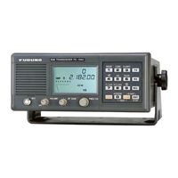
Furuno FS-8000 Operator's Manual (151 pages)
SSB Radiotelephone
Brand:
Furuno
| Category:
Transceiver
| Size: 8 MB
Table of Contents
Safety Instructions
3
Safety Information for the Operator
4
Table of Contents
7
Operator's Guide
10
User Channel
10
ITU/DSC Channel
10
2182 Khz Distress Calling
12
DSC Distress Calling
13
When DSC Terminal with Frequency Remote Control
13
In the Event of Antenna Coupler Failure
14
Antenna Coupler
15
Transceiver Unit
15
Control Unit
15
Introduction
16
Specifications
17
Miscellaneous Functions
19
Compass Safe Distance
19
Precautions
20
System Configuration
21
Operation
22
Front Panel Controls & Indications
22
Controls
23
TX Block Keys
23
RX Block Keys
26
Frequency Control Block Keys
28
Channel Change by Curs & Tune Keys
29
Class of Emission/Time Setting Block Keys
29
Recommended AGC Curve
30
Standard Bandwidth for each Class of Emission
30
Basic Operation
31
Turning the Power on and off
31
Setting Date & Time
31
Setting the Wake-Up Timer
31
Class of Emission Selection
32
Frequency Selection
32
Conventions
32
Viewing the Contents of User CH.
33
Receiving
34
S Meter Indication
34
Scan Receiving
35
Setting Scan Parameters
35
Viewing Scan Parameters
35
Sweep Receiving
36
Setting Sweep Parameters
36
Viewing Sweep Parameters
36
Transmitting
37
Changing Factory Set Tones
37
Test Tone Frequency
37
Side Tone Frequency
37
Change of Specifications
38
Operator-Changeable Specifications
38
Operation of Intercom
39
Control Unit Priority
39
Testing the Transmitter by Dummy Antenna
40
Maintenance
41
General
41
Cleaning
41
Regular Maintenance
42
Self Tests
43
Control Unit & Transceiver Unit
43
Troubleshooting
44
Transceiver Unit Inside View
47
Rectifier Unit, Cover Opened
47
Control Unit, Inside View
48
Error Messages
49
Error Messages for Self Tests
51
PCB Locations
53
Installation
55
Installation & Communication
56
Duplex Communication
56
Connection Method for Simplex Communication
56
Simplex Communication
57
Connections Required for Duplex Communication
57
BK Relay in the Transceiver Unit
57
MF Two-Frequency Communication
58
Antenna BK Relay
58
Antenna
59
Transmitting Antenna
59
Receiving Antenna
59
Mounting the Control Unit
60
Mounting Considerations
60
Location of Front Panel Fixing Screws
60
Separating the Top and Bottom Chassis
60
Wiring
61
Hardware for Mounting the Control Unit
61
Location of Parts Inside the Control Unit
61
How to Use the Terminal Opener
62
MIC Input Terminal
63
Optional Equipment
63
Ground Connection
63
Cable Entries for the Handset
63
Mounting the Transceiver Unit
64
Mounting Dimensions of the Transceiver Unit
64
In the Upper Unit
66
In the Lower Unit
66
Optional Supply of Connector Block Assembly
67
Installation of R. Ant Sel Board
68
Wiring on the Interface Board
71
Making the Ground Connection on the Transceiver Unit
71
Mounting the Antenna Coupler
72
Outdoor Installation
72
Indoor Installation
72
Mounting Dimensions
72
Anti-Moisture Measure
73
Mounting the Coupler Indoors
74
Antenna Coupler, Front Cover Opened
74
Connections on the Coupler Board
75
Grounding the Antenna Coupler
76
Selection of Input Voltage
78
Ground
78
Post Installation Checks and Adjustments
79
Visual Checks
79
Input Voltage Check
79
Control Unit Check
80
Receiver Check
80
Transmitter Check
80
Adjustment of Noise Blanker Level
80
Manual 2182Khz Tuning Preset
81
Alteration of Supply Voltage Setting
83
Checking Voltage
84
Modification of Interface Board
85
Installation of Optional Equipment
86
Dummy Load
86
Antenna Coupler, Top Cover Removed
86
Dummy Load & Antenna BK Relay
90
Connection of External Equipment
94
BK Connection
94
Interface Board
95
Minus BK Line Control
96
CIF/NMEA Connection
97
NBDP Terminal, DSC Terminal, Intership FAX & Selcall
98
Remarks on Connection to NBDP
101
RB-500 Connection
102
Equipment List
103
Complete Set
103
Optional Supply
103
Installation Materials
104
Accessories
106
Wire Antenna Materials
107
Antenna Lead-In Kit
108
Optional Installation Materials
109
Installation Materials for Control Unit
109
Optional Accessories
110
List of Schematic Diagrams
121
Frequency Tables
129
DSC & Distress Frequencies
129
MF Band ITU Telex Frequency Table
139
MF Band ITU SSB Frequency Table
140
Digital Interface (IEC 61162-1 Edition 2)
145
Input Sentences
145
Gga, Gll, Rma, Zda, Rmc
145
GGA - Global Positioning System (GPS) Fix Data
146
GLL - Geographic Position - Latitude and Longitude
147
RMA - Recommended Minimum Navigation Information - Loran C Data
148
RMC - Recommended Minimum Specific GPS/TRANSIT Data
149
ZDA - Data and Time
149
Advertisement
Furuno FS-8000 Operator's Manual (1 page)
SSb Radiotelephone
Brand:
Furuno
| Category:
Telephone
| Size: 0 MB
Advertisement
Related Products
Furuno FS-1503
Furuno FS-1501
Furuno FS-1562-15
Furuno FS-1562-25
Furuno FS-1562
Furuno FS-1552
Furuno FS-5000
Furuno FS-1570
Furuno FS-1550
Furuno FS-2570
Furuno Categories
Marine Radar
Marine Equipment
Sonar
Monitor
GPS
More Furuno Manuals
Login
Sign In
OR
Sign in with Facebook
Sign in with Google
Upload manual
Upload from disk
Upload from URL