Sign In
Upload
Manuals
Brands
Fronius Manuals
Industrial Equipment
Robacta CTC
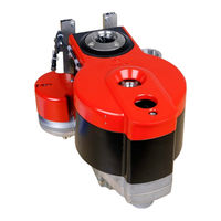
Fronius Robacta CTC Manuals
Manuals and User Guides for Fronius Robacta CTC. We have
2
Fronius Robacta CTC manuals available for free PDF download: Operating Instructions Manual
Fronius Robacta CTC Operating Instructions Manual (80 pages)
Brand:
Fronius
| Category:
Industrial Equipment
| Size: 2 MB
Table of Contents
Deutsch
3
Table of Contents
3
Allgemeines
4
Inhalt dieses Dokumentes
4
Eigenschaften der Datenübertragung
4
Konfigurationsparameter
4
Technische Daten
5
Sicherheit
5
Anschlüsse und Steckerbelegungen
6
Anschlüsse für die Roboter-Steuerung an Robacta FB 8I_8O (Robacta CTC)
6
Anschlüsse für die Roboter-Steuerung an der Geräte-Außenseite von Robacta TX, TX 10I
6
Anschlüsse am Feldbus-Koppler BK9105
6
Steckerbelegung für die RJ45 Ethernet-Anschlüsse
7
Steckerbelegung für Anschluss Versorgung +24 V AIDA
8
Getrennte / Gemeinsame 24 V Spannungsversorgung
9
Getrennte 24 V Spannungsversorgung
9
Gemeinsame 24 V Spannungsversorgung Extern
9
Gemeinsame 24 V Spannungsversorgung Intern
9
Roboter-Steuerung Anschließen
11
Informationen zum Datenkabel
11
Datenkabel der Roboter-Steuerung Anschließen
11
IP-Adresse Einstellen
13
Übersicht
13
IP-Adresse über Bootp Server Einstellen
13
Ein- und Ausgangssignale Reinigungsgeräte
15
Ein- und Ausgangssignale (Stecker I/O 1)
15
Ein- und Ausgangssignale Robacta CTC
22
Anordnung der Feldbus-Klemmen (Optionale Konfiguration)
22
Eingangssignale (von CTC zum Roboter)
22
Ausgangssignale (vom Roboter zu CTC)
22
Zusätzlicher Funktionsumfang von Robacta FB 8I_8O Profinet
23
Ein- und Ausgangssignale Robacta TX
30
Anordnung der Feldbus-Klemmen
30
Eingangssignale (von der Brennerkörper-Wechselstation zum Roboter)
30
Ausgangssignale (vom Roboter zur Brennerkörper-Wechselstation)
31
Ein- und Ausgangssignale Robacta TX 10I
33
Anordnung der Feldbus-Klemmen
33
Eingangssignale (von der Brennerkörper-Wechselstation zum Roboter)
33
Ausgangssignale (vom Roboter zur Brennerkörper-Wechselstation)
34
Ein- und Ausgangssignale Robacta Tx/I TWIN
36
Anordnung der Feldbus-Klemmen
36
Eingangssignale (von der Brennerkörper-Wechselstation zum Roboter)
36
Ausgangssignale (vom Roboter zur Brennerkörper-Wechselstation)
37
Fehlerdiagnose, Fehlerbehebung
38
Anzeigen am Feldbus-Koppler BK9105
38
Leds zur Diagnose der Spannugsversorgung
38
LED am RJ5-Anschluss
39
Leds zur Feldbus-Diagnose
39
Leds zur Diagnose des K-Bus
40
English
43
General
44
Contents of this Document
44
Data Transfer Properties
44
Configuration Parameters
44
Technical Data
45
Safety
45
Connections and Connector Pin Assignments
46
Connections for Robot Controls to Robacta FB 8I_8O (Robacta CTC)
46
Connections for Robot Controls on the Outside of Robacta TX, TX 10I, Tx/I TWIN
46
Connections on the Fieldbus Coupler BK9105
46
Pin Assignment for the RJ45 Ethernet Connections
47
Pin Assignment for Supply Connection Socket +24 V AIDA
47
Separate/Common 24 V Power Supply
48
Separate 24 V Power Supply
48
Common 24 V External Power Supply
48
Common 24 V Internal Power Supply
48
Connecting the Robot Control
50
Data Cable Information
50
Connecting the Robot Control Data Cable
50
Setting the IP Address
52
Overview
52
Setting the IP Address Using Bootp Server
52
Cleaning Device Input and Output Signals
54
Input and Output Signals (I/O 1 Plug)
54
Robacta CTC Input and Output Signals
60
Arrangement of the Fieldbus Terminals (Optional Configuration)
60
Input Signals (from CTC to Robot)
60
Output Signals (from Robot to CTC)
60
Additional Scope of Functions of Robacta FB 8I_8O Profinet
61
Robacta TX Input and Output Signals
68
Fieldbus Terminal Allocation
68
Input Signals (from the Torch Body Change Station to the Robot)
68
Output Signals (from the Robot to the Torch Body Change Station)
69
Robacta TX 10I Input and Output Signals
71
Fieldbus Terminal Allocation
71
Input Signals (from the Torch Body Change Station to the Robot)
71
Output Signals (from the Robot to the Torch Body Change Station)
72
Robacta TX /I TWIN Input and Output Signals
74
Fieldbus Terminal Allocation
74
Input Signals (from the Torch Body Change Station to the Robot)
74
Output Signals (from the Robot to the Torch Body Change Station)
75
Troubleshooting
76
Indicators on the Fieldbus Coupler BK9105
76
Leds for Power Supply Diagnosis
76
LED on the RJ5 Connection Socket
77
Leds for Fieldbus Diagnosis
77
Leds for Communication Bus Diagnosis
78
Advertisement
Fronius Robacta CTC Operating Instructions Manual (56 pages)
Brand:
Fronius
| Category:
Welding Accessories
| Size: 6 MB
Table of Contents
Table of Contents
4
1 Declaration of Conformity
7
2 Technical Specifications
8
Type
9
Dimension
10
Sensor Technology
11
3 Basic Saftey Instructions
13
Explanation of Symbols and Instructions
13
Proper Use
14
Improper Use
14
Obligation to Instruct
15
Safety Devices
15
Systems with Servo- and Frequency Inverters
15
Inspection Obligation
15
Conduct in Case of Hazards and Faults
16
Information Regarding Residual Risks
16
Special Hazard Points
16
Safety and Protection Devices
16
Special Safety Instructions
17
Hazards During Maintenance, Repair and Similar Work
18
Product Monitoring
18
4 Setup and Assembly
19
Place of Installation, Place of Use
19
Alignment and Mounting
19
Protective Conductor Connection on the Stand
19
5 Commissioning / Setup
20
Safety Requirements
20
Initial Commissioning
20
Preparation for Operation
21
Tolerance for Centering and Parallelism
21
Process Preparation for Teaching
22
Signals
23
Spacer
23
Change Spacer
25
Teaching Process
26
Preparation Process
26
Confirmation of Engine Running
27
Cut off Welding Wire
28
Turn off and Remove the Nozzle
30
Cleaning the Contact Tip
32
Actuation of the Magazine (Revolver)
33
Remove Contact Tip
33
Contact Tip Attachement
36
Attachment Nozzle
37
6 Storage and Transport
41
Safety Regulations
41
Symbols on the Cargo
41
Transport Type
41
Handover and Inspection
42
Unpacking and Storage
42
7 Maintenance and Repair
43
Maintenance
43
Cleaning
45
Repair
45
Safety Regulations
45
8 Decommissioning/Dismantling
47
Safety Regulations
47
Decommissioning
47
9 Spareparts
48
Patrlist
49
10 Service
50
Troubleshooting
50
11 Appendix
52
Data on the Different Contact Tips
52
Data on Different Nozzles
53
Elektronic
54
Advertisement
Related Products
Fronius Robacta TX
Fronius Robacta TX/i TWIN
Fronius Robacta Drive CMT G
Fronius Robacta Drive CMT G Pro
Fronius Robacta Drive G
Fronius Robacta Drive CMT-PAP G
Fronius Robacta Drive CMT W
Fronius Robacta Drive CMT W Pro
Fronius Robacta Drive CMT PAP W
Fronius Robacta Drive CMT PAP W Pro
Fronius Categories
Inverter
Welding System
Welding Accessories
Battery Charger
Measuring Instruments
More Fronius Manuals
Login
Sign In
OR
Sign in with Facebook
Sign in with Google
Upload manual
Upload from disk
Upload from URL