Sign In
Upload
Manuals
Brands
Fronius Manuals
Cleaning Equipment
Acerios
Fronius Acerios Manuals
Manuals and User Guides for Fronius Acerios. We have
2
Fronius Acerios manuals available for free PDF download: User Information, Operating Instructions Manual
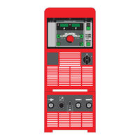
Fronius Acerios User Information (116 pages)
Roboter-Interface
Brand:
Fronius
| Category:
Welding System
| Size: 6 MB
Table of Contents
Deutsch
3
Table of Contents
3
Eingangssignale zur Stromquelle
5
Schweißen ein
5
Roboter Bereit
5
Betriebsarten
5
Master-Kennung Twin
8
Gas Test
8
Drahtvorlauf
9
Drahtrücklauf
10
Positionssuchen (Touch Sensing)
10
Brenner Ausblasen
11
Quellenstörung Quittieren
12
Job-Nummer
12
Programm-Nummer
12
Schweißsimulation
12
Synchropuls Disable
12
SFI Disable
12
Puls-/Dynamik Korrektur Disable
12
Leistungs-Vollbereich
13
Rückbrand Disable
13
Leistung (Sollwert)
13
Lichtbogen-Längenkorrektur (Sollwert)
13
Pulskorrektur (Sollwert)
13
Rückbrand (Sollwert)
13
Dynamic Power Control DPC Enable
14
Zusätzlich Verwendete Signale für den WIG Bereich
15
KD Disable
15
Externe Box
15
Verfahren DC/AC
16
Verfahren DC-/DC
16
Kalottenbildung
16
Pulsen Disable
16
Pulsbereichs-Auswahl
16
Hauptstrom (Sollwert)
16
Externer Parameter (Sollwert)
16
Grundstrom (Sollwert)
17
Duty Cycle (Sollwert)
17
Duty Cycle Disable
17
Grundstrom Disable
17
Drahtgeschwindigkeit Fd.1 (Sollwert)
17
Hochfrequenz Aktiv
17
Zusätzlich Verwendete Signale für den HAP Bereich
18
Pulsen Disable
18
Pulsbereichs-Auswahl
18
Hauptstrom (Sollwert)
18
Externer Parameter (Sollwert)
18
Grundstrom (Sollwert)
18
Duty Cycle (Sollwert)
18
Duty Cycle Disable
18
Grundstrom Disable
18
Hochfrequenz Aktiv
19
Ausgangssignale zum Roboter
20
Lichtbogen Stabil (Stromfluss-Signal)
20
Limitsignal
20
Prozess Aktiv
20
Hauptstrom-Signal
20
Kollisionsschutz
20
Stromquelle Bereit
20
Kommunikation Bereit
20
Error-Nummer
20
Festbrand-Kontrolle
21
Roboter Zugriff
21
Schweißdraht Vorhanden
21
Kurzschluss-Zeit Überschreitung
21
Daten Dokumentation Bereit
21
Puls High
21
Schweißspannung (Istwert)
21
Schweißstrom (Istwert)
21
Motorstrom (Istwert)
21
Lichtbogen-Länge (Istwert)
22
Drahtgeschwindigkeit (Istwert)
22
Leistung Außerhalb Bereich
22
Fehler-Nummer
22
Fehler-Nummer UBST
26
Programmlisten-Beispiel (M 0164)
28
Program List
28
Signalverlauf bei Anwahl über Programm-Nummer und Sollwerte ohne Fehler
30
Signalverlauf bei Anwahl über Job-Nummer ohne Fehler
32
Signalverlauf bei Anwahl über Programm-Nummer und Sollwerte mit Fehler
33
Signalverlauf bei Anwahl über Job-Nummer mit Fehler
35
Signalverlauf bei Anwahl über Job-Nummer mit Limitsignal (Warnung)
36
Signalverlauf bei Anwahl über Job-Nummer mit Limitsignal (Anlagenstopp)
37
Zeitgleiche Anwahl der Signale „Job-Nummer" oder „Programmnummer" und „Schweißen ein
38
Empfohlene Vorgehensweise bei Job-/Programm-Anwahl ohne Kennlinien-Änderung
38
Empfohlene Vorgehensweise bei Job-/Programm-Anwahl mit Kennlinien oder Betriebsart-Änderung
38
Realisierung des Zeitlichen Abstandes
39
Von Fronius Empfohlene Vorgehensweise
38
English
41
Input Signals to the Power Source
43
Welding Start
43
Robot Ready
43
Operating Modes
43
Master Selection Twin
46
Gas Test
46
Wire Inching
46
Wire Retract
47
Touch Sensing
48
Torch Blow out
49
Source Error Reset
49
Job Number
49
Program Number
50
Welding Simulation
50
Synchropuls Disable
50
SFI Disable
50
Pulse/Dynamic Correction Disable
50
Full Power Range
50
Burn-Back Disable
50
Power (Command Value)
50
Arc Length Correction (Command Value)
51
Pulse Correction (Command Value)
51
Burn-Back (Command Value)
51
Dynamic Power Control DPC Enable
51
Other Signals Used for TIG Welding
52
Cold Wire Disable
52
External Box
52
DC/AC Process
53
DC- / DC+ Process
53
Cap Shaping
53
Pulse Disable
53
Pulse Range Selection
53
Main Current (Set Value)
53
External Parameter (Set Value)
53
Base Current (Set Value)
53
Duty Cycle (Set Value)
54
Duty Cycle Disable
54
Base Current Disable
54
Wirefeed Speed Fd.1 (Set Value)
54
High Frequency Active
54
Other Signals Used for HAP Mode
55
Pulse Disable
55
Pulse Range Selection
55
Main Current (Set Value)
55
External Parameter (Set Value)
55
Base Current (Set Value)
55
Duty Cycle (Set Value)
55
Duty Cycle Disable
55
Base Current Disable
55
High Frequency Active
56
Output Signals to the Robot
57
Arc Stable (Current Flow Signal)
57
Limit Signal
57
Process Active
57
Main Current Signal
57
Collision Protection
57
Power Source Ready
57
Communication Ready
57
Error Number
57
Stick Control
58
Robot Access
58
Welding Wire Available
58
Short Circuit Timeout
58
Data Documentation Ready
58
Pulse High
58
Welding Voltage (Real Value)
58
Welding Current (Real Value)
58
Motor Current (Real Value)
58
Arc Length (Real Value)
59
Wire Speed (Real Value)
59
Power Outside Range
59
Error Number
59
Error Number UBST
63
Example of a Program List (M 0164)
65
Program List
65
Signal Waveform When Selecting Via Program Number and Command Values with no Errors
67
Signal Waveform When Selecting Via Job Number with no Errors
69
Signal Waveform When Selecting Via Program Number and Command Values with Errors
70
Signal Waveform When Selecting Via Job Number with Errors
72
Signal Waveform When Selecting Via Job Number with Limit Signal (Warning)
73
Signal Waveform When Selecting Via Job Number with Limit Signal (Machine Stops)
74
Fronius-Recommended Procedures
75
Recommended Procedures for Job/Program Selection Without Changing the Characteristics
75
Recommended Procedures for Job/Program Selection and Changing the Characteristic or Operating Mode
75
Setting the Time Gap
76
Français
77
Signaux D'entrée Vers la Source de Courant
79
Soudage Activé
79
Robot Prêt
79
Modes de Service
79
Identification Maître Twin
82
Gas Test
83
Amenée de Fil
83
Retour de Fil
84
Recherche de Position (Touch Sensing)
85
Soufflage Torche
86
Valider la Panne de Source
86
Numéro de Job
86
Numéro de Programme
86
Simulation du Soudage
87
Synchropuls Disable
87
SFI Disable
87
Correction Arc Pulsé / Dynamique Disable
87
Pleine Puissance
87
Brûlure Retour Disable
87
Puissance (Valeur de Consigne)
87
Correction de la Longueur de L'arc Électrique (Valeur de Consigne)
88
Correction de L'impulsion (Valeur de Consigne)
88
Brûlure Retour (Valeur de Consigne)
88
Dynamic Power Control DPC Enable
88
Autres Signaux Utilisés pour la Plage TIG
89
KD Disable
89
Boîtier Externe
89
ProcéDé DC/AC
90
ProcéDé DC-/DC
90
Formation de Calottes
90
Impulsions Disable
90
Sélection Plage D'impulsions
90
Courant Principal (Valeur de Consigne)
90
Paramètre Externe (Valeur de Consigne)
90
Courant de Base (Valeur de Consigne)
91
Duty Cycle (Valeur de Consigne)
91
Duty Cycle Disable
91
Courant de Base Disable
91
Vitesse D'avance du Fil Fd.1 (Valeur de Consigne)
91
Haute Fréquence Active
91
Autres Signaux Utilisés pour la Plage HAP
92
Impulsions Disable
92
Sélection Plage D'impulsions
92
Courant Principal (Valeur de Consigne)
92
Paramètre Externe (Valeur de Consigne)
92
Courant de Base (Valeur de Consigne)
92
Duty Cycle (Valeur de Consigne)
92
Duty Cycle Disable
92
Courant de Base Disable
92
Haute Fréquence Active
93
Signaux de Sortie Vers le Robot
94
Arc Électrique Stable (Signal D'arrivée de Courant)
94
Signal de Limite
94
Processus Actif
94
Signal de Courant Principal
94
Protection Contre les Collisions
94
Source de Courant Prête
94
Communication Prête
94
Numéro D'erreur
95
Contrôle Collage du Fil
95
Accès Robot
95
Fil de Soudage Disponible
95
Dépassement Durée Court-Circuit
95
Données Documentation Prêtes
95
Puls High
95
Tension de Soudage (Valeur Réelle)
95
Courant de Soudage (Valeur Réelle)
96
Courant Moteur (Valeur Réelle)
96
Longueur de L'arc Électrique (Valeur Réelle)
96
Vitesse D'avance du Fil (Valeur Réelle)
96
Puissance Hors Plage
96
Numéro D'erreur
97
Numéro D'erreur UBST
101
Exemple pour une Liste de Programme (M 0164)
102
Liste des Programmes
102
Parcours du Signal Lors de la Sélection Par le Numéro de Programme et Valeurs de Consigne Sans Erreur
104
Parcours du Signal Lors de la Sélection du Numéro de Job Sans Erreur
106
Parcours du Signal Lors de la Sélection Par le Numéro de Programme et Valeurs de Consigne Avec Erreur
107
Parcours du Signal Lors de la Sélection du Numéro de Job Avec Erreur
109
Parcours du Signal Lors de la Sélection du Numéro de Job Avec Signal de Limite (Avertissement)
110
Parcours du Signal Lors de la Sélection du Numéro de Job Avec Signal de Limite (Arrêt de L'installation)
111
Procédures Recommandées Par Fronius
112
Sélection Simultanée des Signaux " Numéro de Job " ou " Numéro de Programme " et " Soudage Activé
112
Ristiques
112
Procédure Recommandée pour la Sélection Job/Programme Avec Modification des Courbes Caracté- Ristiques ou du Mode de Service
113
Réalisation de L'intervalle de Temps
113
Advertisement
Fronius Acerios Operating Instructions Manual (84 pages)
Brand:
Fronius
| Category:
Cleaning Equipment
| Size: 0 MB
Table of Contents
Table of Contents
3
Safety Instructions
6
Explanation of Safety Instructions
6
General
6
Intended Use
7
Environmental Conditions
7
Obligations of the Operating Company
7
Obligations of Personnel
7
Grid Connection
8
Personal Protection and Protection of Others
8
Data Regarding Noise Emission Values
8
Danger from Toxic Gases and Vapors
9
Danger from Fire
9
Hazards from Grid Current and Process Current
10
Stray Currents
11
EMC Device Classifications
11
EMC Measures
11
EMF Measures
12
Particular Hazard Areas
12
Impaired Plasma Surface Treatment
13
Danger from Gas Cylinders
13
Danger Due to Escaping Gas
13
Safety Measures at the Setup Location and During Transport
14
Safety Measures in Normal Operation
14
Maintenance and Repair
15
Safety Inspection
15
Disposal
15
Safety Symbols
16
Data Backup
16
Copyright
16
General Information
17
General
19
Device Concept
19
Operating Principle
19
Application Areas
20
System Configurations
20
Operating Controls and Connections
21
Control Panel
23
General
23
Safety
23
Control Panel
24
Shortcut Keys - Special Functions
27
General
27
Key Lock
27
Show Software Version, Runtime, and Coolant Flow
28
Connections, Switches, and Mechanical Components
29
Acerios Connections
29
Installation and Startup
31
Before Installation and Initial Operation
33
Safety
33
Minimum Equipment
33
Intended Use
33
Setup Regulations
33
Grid Connection
34
Installation
35
Safety
35
General
35
Commissioning
37
Connecting the Gas Cylinder
37
Connecting the Plasma Torch
37
Plasma Surface Treatment
39
Overloaded Electrode
41
Description of Operating Modes
42
2-Step Mode
42
Plasma Surface Treatment
43
Safety
43
Process Parameters
43
Plasma Surface Treatment
44
Special Functions and Options
45
Arc Break Monitoring Function
45
Ignition Time-Out Function
45
Plasma Pulsing
45
Hold-Function
46
Job Mode
47
General
47
Abbreviations
47
Saving a Job
48
Job Retrieval
49
Copying/Overwriting a Job
50
Deleting a Job
52
Setup Settings
53
The Setup Menu
55
General
55
Accessing the Setup Menu
55
Accessing the 2Nd Level Setup Menu
55
Adjusting Parameters
55
Parameters in the Setup Menu
56
Parameters in the 2Nd Level Setup Menu
57
Exiting the 2Nd Level Setup Menu
60
Exiting the Setup Menu
60
Displaying Plasma System Resistance R
61
General
61
Measuring Plasma System Resistance R
61
Displaying Plasma System Inductance L
62
General Information on Plasma System Inductance L
62
The Gas Menu
63
General
63
Accessing the Gas Menu
63
Adjusting Parameters
63
Parameters in the Gas Menu
63
Exiting the Setup Menu
64
The Job Correction Menu
65
General
65
Accessing the Job Correction Menu
65
Adjusting Parameters
65
Correctable Parameters in the Job Correction Menu
65
Exiting the Job Correction Menu
67
Troubleshooting and Maintenance
69
Troubleshooting
71
General
71
Safety
71
Displayed Service Codes
71
Power Source Troubleshooting
75
Service, Maintenance and Disposal
77
General
77
Safety
77
At Every Start-Up
77
Every 2 Months
77
Every 6 Months
78
Disposal
78
Appendix
79
Technical Data
81
Special Voltage
81
Acerios
81
Explanation of Footnotes
81
Advertisement
Related Products
Fronius Acctiva Classic
Fronius Acctiva Seller
Fronius Acctiva Professional Flash JP
Fronius Acctiva Seller UCN
Fronius Acctiva 2010E
Fronius Acctiva Professional Flash UCN CN
Fronius Acctiva Professional 35 A UCN
Fronius Acctiva Twin
Fronius AccuPocket 150
Fronius MagicCleaner 150 MV/B
Fronius Categories
Inverter
Welding System
Welding Accessories
Battery Charger
Measuring Instruments
More Fronius Manuals
Login
Sign In
OR
Sign in with Facebook
Sign in with Google
Upload manual
Upload from disk
Upload from URL