Sign In
Upload
Manuals
Brands
Eurotherm Manuals
Controller
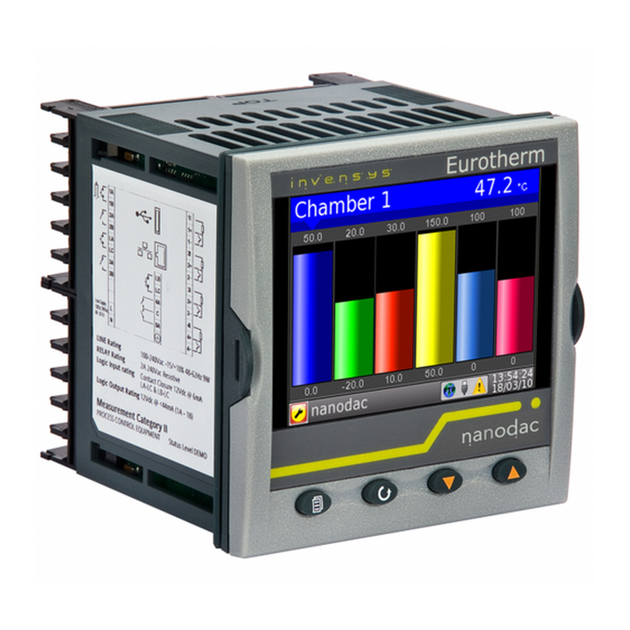
Nanodac
Eurotherm Nanodac Manuals
Manuals and User Guides for Eurotherm Nanodac. We have
1
Eurotherm Nanodac manual available for free PDF download: User Manual
Eurotherm Nanodac User Manual (392 pages)
Recorder Controller
Brand:
Eurotherm
| Category:
Controller
| Size: 13 MB
Table of Contents
Table of Contents
3
Introduction
14
3 Operation
15
Electrical Installation
17
Low Voltage Option
19
Operation
20
On Screen Help
21
Process Variable Display
22
Status Bar Icons
23
Breaks in Recording
26
Go to View
27
History
30
Demand Archiving
31
Login
33
Display Modes
35
Horizontal Trend Mode
36
Horizontal Bargraph Mode
37
Alarm Panel
38
Control Loop1/Loop2
39
Cascade Display Mode
40
Programmer Display Mode
41
Steriliser Display Mode
53
Promote List
57
Modbus Master Display Mode
58
Ethernet/Ip Display Mode
60
History Options Menu
67
Text Entry
68
4 Configuration
69
Instrument Menu
70
Clock
71
Locale
72
Display Configuration
73
Info Menu
75
Upgrade
76
Security Menu
77
I/O Fitted
79
Save/Restore
80
Input Adjust
81
Output Adjust
84
Network Menu
85
Interface
85
Archiving
87
FTP Server
89
Modbus TCP
90
Group Configuration
91
Group Trend Configuration
91
Group Recording Configuration
92
Input Channel Configuration
93
Channel Main
94
Channel Trend Configuration
98
Alarm 1 Menu
99
Alarm 2 Menu
100
Alarm Types
101
Virtual Channel Configuration
103
Maths Channel Configuration
103
Totaliser Configuration
105
Wiring Example Using a Counter in Combination with a Totaliser
109
Counter Configuration
110
Loop Option Configuration
112
Main Menu Parameters
113
Setup Menu Parameters
113
Tune Menu Parameters
114
PID Menu Parameters
115
Setpoint Menu Parameters
116
Output Menu Items
117
Loop Diagnostics
119
Advanced Loop Configuration
120
Advanced Loop Main Menu
121
Advanced Loop Setup Menu
122
Advanced Loop Tune Menu
123
Advanced Loop Master PID Menu
126
Advanced Loop Slave PID Menu
127
Advanced Loop Master SP Menu
129
Advanced Loop Slave SP Menu
131
Advanced Loop Output Menu
133
Advanced Loop Diagnostics Menu
136
Programmer Configuration
137
Programmer Features Menu
138
Programmer FTP Menu
140
Programmer Setup Menu
141
Programmer Run Menu
144
Connecting the Programmer to a Loop
146
Configuration by Modbus Comms
148
Modbus Master Configuration
149
Slave Main Menu
150
Slave Diagnostics Menu
151
Modbus Master Data Configuration
152
Ethernet/Ip Configuration
155
Ethernet/Ip Configuration Main Menu
155
Implicit Inputs/Outputs
156
Explicit Inputs/Outputs
156
Web Server
158
Configuration Display
158
Digital I/O
159
Digital Input/Output
159
Relay Outputs
159
Digital Inputs
160
Digital Outputs
160
DC Output
161
Configuration Display
161
User Lin
162
User Linearisation Table Rules
162
Custom Messages
163
Zirconia Block Option
163
Definitions
163
Configuration
164
Zirconia Probe Wiring
167
Steriliser Option
168
Configuration Parameters
168
Humidity Block Option
170
Configuration Parameters
170
Bcd Input
171
Input Rules
171
Configuration
171
Logic (2 Input) Block
172
Parameters
172
Logic (8 Input) Block
173
Parameters
173
Schematic
173
Invert Input Decoding Table
174
Multiplexer Block
175
Configuration Parameters
175
Math (2 Input)
176
Parameters
176
Sample and Hold Details
177
Timer
178
Parameters
178
Timer Modes
178
User Values
180
Parameters
180
Alarm Summary
181
Real Time Event Configuration
182
5 Modbus Tcp Slave Comms
183
Installation
183
Introduction
183
Function Codes
183
Data Types
184
Invalid Multiple Register Writes
184
Master Communications Timeout
184
Non-Volatile Parameters in EEPROM
184
Parameter List
188
6 Itools
266
Itools CONNECTION
267
Ethernet (Modbus TCP) Communications
267
Direct Connection
269
Scanning for Instruments
270
Graphical Wiring Editor
271
Tool Bar
272
Wiring Editor Operating Details
272
Parameter Explorer
280
Parameter Explorer Detail
281
Explorer Tools
282
Watch/Recipe Editor
283
Watch Recipe Toolbar Icons
284
Programmer Option
285
Digital Event Display
287
Adding and Deleting Segments
288
Loading and Saving Programs
289
Context Menus
290
Programmer Menu
291
Two Channel Programs
292
To Set up OEM Security
293
User Wiring
296
7 User Wiring
297
Counter Example
298
8 USB Devices
301
Usb Keyboard
302
A Technical Specification
303
Appendix A: TECHNICAL SPECIFICATION
304
A2 Recorder Specification
304
A3 Analogue Input Specification
305
A4 Relay and Logic I/O Specification
307
A7.2 Application Blocks
308
B Control Loops
309
Appendix B CONTROL LOOPS
310
B2.2 Types of Control Loop
310
Integral Term
311
Manual Mode
312
B2.3 Loop Parameters
313
B2.4 Tuning
315
Under Damped
316
Rate
317
Autotune and Sensor Break
318
Example 1: Autotune from below Sp (Heat/Cool)
319
Example 2: Autotune from below Sp (Heat Only)
320
Example 3: Autotune at Sp (Heat /Cool)
321
At.r2G
322
Failure Modes
323
EXAMPLE 4: When Tune R2G = R2GPD, Autotune from below Setpoint
324
Cutback Values
325
B2.5 Setpoint
326
Note
329
B2.6 Output
330
Safe
331
Linear
332
Control Action
333
B2.7 Diagnostics
336
C Reference
337
Appendix C: REFERENCE
338
C2 Setting up an Ftp Server Using Filezilla
338
C2.2 Server Setup
340
C2.3 Pc Setup
341
C2.5 Archive Activity
342
C3 Function Block Details
343
C4 Tcp Port Numbers
344
D Configuration Menu Overview
345
Appendix D: CONFIGURATION MENU OVERVIEW
346
D1 Instrument Configuration Menus
346
D2 Network Configuration Menus
347
D3 Group Configuration Menu
348
D5 Virtual Channel Configuration Menu
349
D6 Loop Configuration Menus
350
D7 Advanced Loop Configuration Menus
351
D8 Programmer Configuration
353
D9 Modbus Master Configuration
354
D10 Ethernet/Ip Configuration
355
D12 Digital I/O Configuration Menus
356
D16 Zirconia Configuration Menus
357
D17 Steriliser Configuration Menu
358
D20 Logic 2 Input Block Confguration Menu
359
D24 Timer Configuration Menu
360
E Web Server
361
E.1.4 Home
362
E.1.6 Contact
363
E.1.7 Bar Graph
364
E.1.8 Line Graph
365
E.1.9 Numeric
366
E.1.11 Message Summary
367
E.1.13 Historical Line
368
E.1.14 Status Icons
369
F Labview Driver
371
F Appendix F: Labview Driver . . . . . . . . . . . . . . . . . . . . . . . . . . . . . . . 361
374
F.2 Application Example 2 - Program Load by Program Number
374
F.3 Application Example 3 Steriliser
375
F.5 Full Driver Capabilities List
376
Index
377
Advertisement
Advertisement
Related Products
Eurotherm 2416
Eurotherm 2500
Eurotherm 2604
Eurotherm 2704
Eurotherm 3204
Eurotherm 3208
Eurotherm 32h8
Eurotherm 3500 series
Eurotherm 3504
Eurotherm Categories
Controller
Temperature Controller
Voice Recorder
Measuring Instruments
DC Drives
More Eurotherm Manuals
Login
Sign In
OR
Sign in with Facebook
Sign in with Google
Upload manual
Upload from disk
Upload from URL