Sign In
Upload
Manuals
Brands
ESD Manuals
Gateway
C.2924.62
ESD C.2924.62 Manuals
Manuals and User Guides for ESD C.2924.62. We have
1
ESD C.2924.62 manual available for free PDF download: Manual
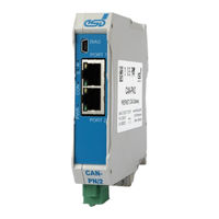
ESD C.2924.62 Manual (122 pages)
Fieldbus Gateway for connecting PROFINET-IO with CAN and CAN FD
Brand:
ESD
| Category:
Gateway
| Size: 4 MB
Table of Contents
Table of Contents
9
Figure 1: PROFINET Device to CAN
12
Figure 2: PROFINET Device to CAN FD
12
Figure 3: Block Circuit Diagram
12
Figure 4: Connecting Diagram of CAN-PN/2 (C.2924.02)
15
Table 1: Description of PROFINET IO Leds
16
Figure 5: Leds of CAN-PN/2 (C.2924.02)
16
Table 2: Indicator States of the Status Leds
17
Table 3: Description of Status Leds
17
Figure 6: CAN-PN/2-FD with Name Plate (Example)
18
Figure 7: CAN-PN/2-FD with Led/Connector Label (Example)
18
Table 4: Hardware Installation
19
Figure 8: Basic Functionality of the Firmware
21
Table 5: Manual Installation of the RNDIS Driver
23
Table 6: Configuration Quick Start Guide
24
Figure 9: Manage GSDML Files
25
Figure 10: Inserting the CAN-PN/2 (Example)
25
Figure 11: Not Assigned CAN-PN/2 (Example)
26
Figure 12: Assigned CAN-PN/2 (Example)
26
Figure 13: Assign IP Address and Device Name of the Configuration
27
Figure 14: Assign IP Address and Device Name of the Gateway
28
Figure 15: Adding Modules to the CAN-PN/2
29
Figure 16: Compile Hardware and Software (Detail)
30
Figure 17: Download Hardware and Software to Device (Detail)
30
Figure 18: Toolbar with Go Online Button
31
Figure 19: Toolbar Online Device Overview
31
Table 7: Configuration Errors
32
Figure 20: Module Parameters
33
Figure 21: PLC Address Space of the Modules (Detail)
33
Table 8: CAN Interface Parameter
34
Table 9: CAN FD Interface Parameter
34
Figure 22: CAN Interface Parameter
34
Figure 23: CAN FD Interface Parameter
34
Table 10: Input Parameter
35
Figure 24: Input Parameter
35
Table 11: CAN FD Input Parameter
36
Figure 25: CAN FD Input Parameter
36
Table 12: Output Parameter
37
Figure 26: Output Parameter
37
Table 13: CAN FD Output Parameter
38
Figure 27: CAN FD Output Parameter
38
Table 14: Static Output Parameter
39
Figure 28: Static Output Parameter
39
Table 15: CAN Frame Structure
40
Table 16: RX-FIFO General Parameter
41
Table 17: RX-FIFO CAN Identifier Parameter
41
Figure 29: RX-FIFO General Parameter
41
Table 18: RX-FIFO Inputs
42
Table 19: RX-FIFO Outputs
42
Figure 30: RX-FIFO CAN Identifier Parameter
42
Table 20: CAN FD RX-FIFO Inputs
43
Table 21: TX-FIFO Parameter
44
Table 22: TX-FIFO Inputs
44
Table 23: TX-FIFO Outputs
44
Figure 31: TX-FIFO Parameter
44
Table 24: CAN FD TX-FIFO Inputs
45
Table 25: CAN Bus States
46
Table 26: Busload Parameter
46
Figure 32: Busload Parameter
46
Table 27: Communication Window Inputs
47
Table 28: Communication Window Outputs
48
Table 29: Communication Window Commands
49
Figure 33: Example In-Counter and Out-Counter
51
Table 30: In-Counter and Out-Counter Pseudo Code
52
Table 31: DLC and Flags
53
Table 32: DLC Classical CAN
53
Table 33: DLC CAN FD
53
Table 34: CAN Frame Flags
53
Table 35: CAN ID Filter
54
Table 36: CAN ID Filter Example
54
Table 37: CAN Format Parameter 1
55
Table 38: CAN Format Parameter 2
55
Table 39: CAN-PN/2 Alarms
56
Table 40: CAN-PN/2 Read Records
59
Table 41: CAN-PN/2 Write Records
60
Table 42: Read Record Read CAN Statistic (0X30/0X31)
61
Table 43: Read Record Read Number of Remaining Frames in the Record Handle (0X300)
61
Table 44: Read Record Read CAN Frame from the Record Handle (0X301)
62
Table 45: Read Multiple CAN Frames from the Record Handle (0X302)
63
Table 46: Read Record Read CAN FD Frame from the Record Handle (0X303)
64
Table 47: Read Record Read Multiple CAN FD Frames from the Record Handle (0X304)
65
Table 48: Write Record Add CAN Identifier to RX-FIFO (0X20)
67
Table 49: Write Record Delete CAN Identifier to RX-FIFO (0X21)
68
Table 50: Write Record Send CAN Frame (0X101)
69
Table 51: Write Record Send Multiple CAN Frame (0X101)
69
Table 52: Write Record Send CAN FD Frame (0X103)
70
Table 53: Write Record Send Multiple CAN FD Frame (0X104)
71
Table 54: Read Record PLC Parameter
72
Table 55: Write Record PLC Parameter
73
Table 56: Firmware Update
74
Table 57: CAN Monitoring
75
Figure 34: CAN Control Panel
75
Figure 35: Monitoring the CAN Bus with Canreal
76
Figure 36: Invalid CAN Data-Phase Bitrate
78
Figure 37: Faulty CAN Bus
79
Figure 38: Duplicates Unique Modules
80
Figure 39: Enable CAN FD
80
Support by Esd
81
Figure 40: Default Tag Table
90
Table 58: General Data of the Module
96
Table 59: CPU and Memory
96
Table 60: Connectors, Accessible from Outside
97
Table 61: Data of the PROFINET IO Interface
97
Table 62: Data of the USB Device Interface
97
Table 63: Data of the CAN Interface
98
General Rules
105
Figure 41: CAN Wiring for Light Industrial Environment
105
Termination Resistor
106
Figure 42: Example for Proper Wiring with Single Shielded Single Twisted Pair Wires
106
Heavy Industrial Environment (Double Twisted Pair Cable)
107
Figure 43: CAN Wiring for Heavy Industrial Environment
107
Device Cabling
108
Figure 44: Example of Proper Wiring with Single Shielded Double Twisted Pair Cables
108
Electrical Grounding
109
Bus Length
109
Table 64: Recommended Cable Lengths at Typical Bit Rates (with Esd-CAN Interfaces)
109
Examples for CAN Cables
110
Cable for Light Industrial Environment Applications (Two-Wire)
110
Cable for Heavy Industrial Environment Applications (Four-Wire)
110
CAN Troubleshooting Guide
111
Figure 45: Simplified Diagram of a CAN Network
111
Electrical Grounding
112
Short Circuit in CAN Wiring
112
Correct Voltage Levels on CAN_H and CAN_L
112
Figure 46: Simplified Schematic Diagram of Ground Test Measurement
112
CAN Transceiver Resistance Test
113
Figure 47: Measuring the Internal Resistance of CAN Transceivers
113
Software Licenses
115
Rd Party Software License Terms
115
Licence Conditions of the Software Modules
115
Yocto-Linux License Modules
115
Others
118
Declaration of Conformity
119
PNO Certificates
120
Can-Pn/2 (C.2924.02)
120
Can-Pn/2-Fd (C.2924.62)
121
Order Information
122
Table 65: Order Information Hardware
122
Table 66: Available Manuals
122
Advertisement
Advertisement
Related Products
ESD C.2920.02
ESD C.2907.02
ESD C.2909.02
ESD C.2922.02
ESD C.2921.02
ESD C.2924.02
ESD C.2931.02
ESD C.2932.62
ESD C.2932.02
ESD C.2051.07
ESD Categories
Recording Equipment
Computer Hardware
Gateway
PCI Card
Control Unit
More ESD Manuals
Login
Sign In
OR
Sign in with Facebook
Sign in with Google
Upload manual
Upload from disk
Upload from URL