Sign In
Upload
Manuals
Brands
Ergon Manuals
Construction Equipment
60800N
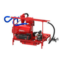
Ergon 60800N Construction Equipment Manuals
Manuals and User Guides for Ergon 60800N Construction Equipment. We have
1
Ergon 60800N Construction Equipment manual available for free PDF download: Operator's & Parts Manual
Ergon 60800N Operator's & Parts Manual (78 pages)
Brand:
Ergon
| Category:
Construction Equipment
| Size: 3 MB
Table of Contents
Table of Contents
5
1 About this Manual
11
How to Use this Manual
11
2 Safety Precautions
13
General Safety
13
Personal Safety
13
Equipment or Operational Safety
14
California Proposition 65
15
All Crafco Inc. Equipment
15
All Crafco Inc. Equipment Using a Gasoline Engine
15
Safety Symbols and Notices
16
Table 2-1 Safety Symbols and Notices
16
Table 2-2 Safety Symbols and Notices (Continued)
17
3 Limited Warranty
19
Warranty Claim Instructions
20
4 Machine Specifications
21
Table 4-1 Machine Specifications
21
5 Operating Instructions
23
Table 5-1 Preparing the Machine for Start up
23
Table 5-2 Preparing the Machine for Start up (Continued)
24
Figure 5-1 Hydraulic Pump and Reservoir
25
Figure 5-2 Rotary Blower Fluid Level
25
Figure 5-3 Compressor Fluid Level
26
Figure 5-4 Filter Housing Cutaway
26
Starting the Blower Engine
27
Table 5-3 Blower Engine Starting Instructions
27
Starting the Compressor Engine
28
Table 5-4 Starting the Compressor Engine
28
Cold Weather Starting
29
Battery
29
Stopping the Blower Engine
29
Stopping the Compressor Engine
29
Table 5-5 Cold Weather Starting Hints
29
Table 5-6 Stopping the Blower Engine
29
Table 5-7 Stopping the Compressor Engine
29
Compressor Operating Principles
30
Air Compressor
30
Oil Separation and Cooling
30
Minimum Pressure Check Valve
30
Filtration
30
Automatic Overheat Shut down
30
Filtering System
31
Cyclonic Separator
31
Table 5-8 Cyclonic Separator
31
Main Cartridge Filter
32
Figure 5-5 Debris Storage Bucket
32
Table 5-9 Cyclonic Separator (Continued)
32
Table 5-10 Main Cartridge Filter
32
Table 5-11 Main Cartridge Filter (Continued)
33
HEPA after Filter
34
Figure 5-6 HEPA Filter & Housing
34
Table 5-12 Main Cartridge Filter (Continued)
34
Table 5-13 HEPA Filter Access
34
Table 5-14 HEPA Filter Access (Continued)
35
Debris Storage Tank
36
Figure 5-7 Debris Storage Tank Door
36
Figure 5-8 Debris Storage Tank Switch
36
Table 5-15 Emptying the Debris Storage Tank
36
EZ Glide Vacuum Wand
37
Table 5-16 Vacuum Wand Operation
37
Figure 5-9 Wand Wheel Spacers
38
Figure 5-10 Wand Routed Crack Brush Location
38
Mounting Crackvac on a Truck or Trailer
39
Figure 5-11 Truck Mounted Unit
39
Table 5-17 Mounting Crackvac on a Truck or Trailer
39
6 Maintenance Instructions
41
Engine Oil Recommendations
41
Oil Type
41
Figure 6-1 Oil Viscosity Chart
41
Fuel Recommendations
42
General Recommendations
42
Fuel Type
42
Gasoline/Alcohol Blends
42
Gasoline/Ether Blends
42
Evaporative Emission Control System
43
Battery
43
Battery Recharging (Compressor Battery)
43
Periodic Maintenance
44
Maintenance Schedule
44
Table 6-1 Maintenance Schedule
44
Service Instructions
46
General Maintenance Parts
46
Table 6-2 Service Instructions
46
Table 6-3 General Maintenance Parts
46
Rotary Air Blower
47
Bearing Lubrication
47
Oil Service
47
V-Belts
47
Storing Procedures
47
Hydraulic System
48
Suction and Exhaust Hoses
48
EZ Glide Wand Assembly
48
Compressor
48
Compressor Engine
48
Compressor Oil
49
Blowdown Muffler
49
Table 6-4 Changing Compressor Oil
49
Pressure Relief Valve
50
Coalescing Filter
50
Table 6-5 Testing the Blowdown Muffler
50
Table 6-6 Testing the Pressure Relief Valve
50
Table 6-7 Replacing the Coalescing Filter
50
Air Intake Filter
51
Figure 6-2 Blowdown Muffler, Relief Valve, Coalescing Filter
51
Figure 6-3 Compressor Air Filter Housing
51
Table 6-8 Replacing the Coalescing Filter (Continued)
51
Compressor Drive Belt
52
Figure 6-4 Replacing Compressor Drive Belt
52
Table 6-9 Replacing the Compressor Drive Belt
52
7 How to Use a Multimeter
53
Checking DC Voltage with a Multimeter
53
Checking Resistance (Ohms)
53
Checking Wire Continuity
53
Figure 7-1 Standard Multimeter
54
Figure 7-2 Clamp-On Amp Meter/Multimeter
54
8 Troubleshooting
55
Table 8-1 Trouble Shooting Guide Vacuum System
55
Table 8-2 Trouble Shooting Guide Compressor System
56
Table 8-3 Trouble Shooting Guide Compressor System (Continued)
57
Table 8-4 Trouble Shooting Guide Hydraulics
58
Figure 8-1 Compressor Wiring Schematic
59
Figure 8-2 Hydraulic Power Pack Wiring Schematic
60
9 Illustrated Parts List
61
About the Illustrated Parts List
61
Ordering Crafco Parts
61
Crackvac Parts List
62
Figure 9-1 Right, Front, ISO View
62
Table 9-1 Right, Front ISO View Parts List
63
Figure 9-2 Left, Rear ISO View
64
Table 9-2 Left, Rear ISO View Parts List
65
Figure 9-3 Bottom View
66
Table 9-3 Bottom View Parts List
67
Blower Drive Components Parts List
68
Figure 9-4 Blower Drive Components
68
Table 9-4 Blower Drive Components Parts List
69
Figure 9-5 Evaporative Emission System
70
Table 9-5 Evaporative Emission System Parts List
70
Suction Wand Assembly Parts List
72
Figure 9-6 Suction Wand Assembly
72
Table 9-6 Suction Wand Assembly Parts List
73
Compressor Assembly Parts List
74
Figure 9-7 Compressor Assembly (60802N)
74
Table 9-7 Compressor Assembly Parts List
74
Table 9-8 Compressor Assembly Parts List (Continued)
75
Advertisement
Advertisement
Related Products
Ergon 60900N
Ergon 21300
Ergon 21340
Ergon 21350
Ergon CRAFCO 100CFM
Ergon Crafco 100G
Ergon Crafco 30
Ergon Crafco E-Z 49000N
Ergon Crafco EZ Patcher
Ergon Crafco Patcher 4
Ergon Categories
Bicycle Accessories
Construction Equipment
Accessories
Farm Equipment
Mixer
More Ergon Manuals
Login
Sign In
OR
Sign in with Facebook
Sign in with Google
Upload manual
Upload from disk
Upload from URL