Table of Contents
Advertisement
Quick Links
Advertisement
Table of Contents
Troubleshooting

Related Manuals for Ergon Crafco 100G


Summary of Contents for Ergon Crafco 100G
- Page 1 CRACK-VAC MODEL 100G Operator/Parts Manual – 26627N Revision O...
- Page 2 Fill in appropriate fields that apply to this machine Machine S/N: _ _______________________________ Engine S/N: ________________________________ Blower S/N: _________________________________ Compressor Engine S/N: ______________________ Compressor S/N: _____________________________...
- Page 3 Crack-Vac Model 100G Manual Revisions Revision Date...
- Page 4 CRACK-VAC MODEL 100G P/N 60800N CRACK-VAC MODEL 100G with COMPRESSOR P/N 60900N...
-
Page 5: Table Of Contents
Crack-Vac Model 100G Manual Table of Contents 1.0 About This Manual ..........................1-1 1.1 How to use this manual: ........................1-1 2.0 Safety Precautions ..........................2-1 2.1 General Safety ............................2-1 2.2 Personal Safety ............................ 2-1 2.3 Equipment or Operational Safety ......................2-2 2.4 California Proposition 65........................ - Page 6 Crack-Vac Model 100G Manual Table of Contents General Recommendations ....................6-2 Fuel Type ..........................6-2 Gasoline/Alcohol Blends ....................6-2 Gasoline/Ether Blends......................6-2 6.3 Evaporative Emission Control System ....................6-3 6.4 Battery ..............................6-3 Battery Recharging (compressor battery) ................6-3 6.5 Periodic Maintenance .......................... 6-4 6.6 Maintenance Schedule ........................
- Page 7 Crack-Vac Model 100G Manual List of Figures Figure 5-1 Hydraulic Pump and Reservoir ....................5-3 Figure 5-2 Rotary Blower Fluid Level ......................5-3 Figure 5-3 Compressor Fluid Level ......................5-4 Figure 5-4 Filter Housing Cutaway ......................5-4 Figure 5-5 Debris Storage Bucket ......................5-10 Figure 5-6 HEPA Filter &...
- Page 8 Crack-Vac Model 100G Manual List of Tables Table 2-1 Safety Symbols and Notices ....................... 2-4 Table 2-2 Safety Symbols and Notices (continued) ................... 2-5 Table 4-1 Machine Specifications ......................4-1 Table 5-1 Preparing the Machine for Start Up ................... 5-1 Table 5-2 Preparing the Machine for Start Up (continued) ...............
- Page 9 Crack-Vac Model 100G Manual List of Tables Table 9-9 Compressor Assembly Parts List (continued) ................9-16...
-
Page 11: About This Manual
Crack-Vac Model 100G Manual Chapter 1 Introduction 1.0 About This Manual This manual is supplied with each new Crafco Crack-Vac Model 100G. The manual assists your machine operators in the proper use of the Crack-Vac and provides information about the machine’s mechanical functions for trouble-free operation. -
Page 13: Safety Precautions
Crack-Vac Model 100G Manual Chapter 2 Safety 2.0 Safety Precautions For more in-depth safety information, please see Safety Manual (P/N 26221) which comes with the machine. Or contact your nearest authorized Crafco Distributor at crafco.com/Distributors. 2.1 General Safety • Crafco, Inc. assumes no liability for an accident or injury incurred through improper use of the machine. -
Page 14: Equipment Or Operational Safety
Crack-Vac Model 100G Manual Chapter 2 Safety 2.3 Equipment or Operational Safety • Do not operate the machine in buildings or work areas that do not have sufficient airflow. • Always keep a correctly maintained fire extinguisher near the machine and know how to use •... -
Page 15: California Proposition 65
Crack-Vac Model 100G Manual Chapter 2 Safety 2.4 California Proposition 65 The state of California currently maintains a list of chemicals that can cause cancer, birth defects or other reproductive harm. Your Crafco, Inc. equipment comes with the following warnings All Crafco Inc. -
Page 16: Safety Symbols And Notices
Crack-Vac Model 100G Manual Chapter 2 Safety 2.5 Safety Symbols and Notices Important safety symbols and notices are marked on the machine and in this manual. Failure to comply could result in equipment damage, operational malfunction, serious injury, or death. Please read and comply with all symbols and notices. -
Page 17: Table 2-2 Safety Symbols And Notices (Continued)
Crack-Vac Model 100G Manual Chapter 2 Safety Table 2-2 Safety Symbols and Notices (continued) Symbol Item Remark Crush Hazard Keep feet and legs clear. Pinch Hazard Keep hands and feet clear. Exhaust Hazard Avoid breathing engine exhaust. Do not use hands to search for leaks, use cardboard High Pressure Fluid Hazard instead. -
Page 19: Limited Warranty
Crack-Vac Model 100G Manual Chapter 3 Warranty Information 3.0 Limited Warranty Crafco, Inc. (Manufacturer), or one of its affiliated distributors, will replace for the original purchaser free of charge any parts found upon examination by the Manufacturer, to be defective in material or workmanship. -
Page 20: Warranty Claim Instructions
Crack-Vac Model 100G Manual Chapter 3 Warranty Information 3.1 Warranty Claim Instructions Crafco, Inc. warrants parts and machinery purchased through Crafco or one of its affiliated distributors for two years from the invoice date. Wear items are not covered under the Crafco, Inc. limited warranty. -
Page 21: Machine Specifications
Crack-Vac Model 100G Manual Chapter 4 Machine Specifications 4.0 Machine Specifications Table 4-1 Machine Specifications P/N 60800N NON-COMPRESSOR P/N 60900N COMPRESSOR Specification UNIT UNIT Holding Tank Capacity 100 Gallons Tank Construction Heavy Duty Steel 16” Full Opening Tank Opening Size Model - Command PRO CH-752 Engine (Blower) –... -
Page 23: Operating Instructions
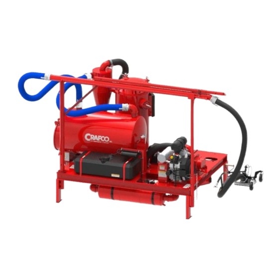
Crack-Vac Model 100G Manual Chapter 5 Operating Instructions 5.0 Operating Instructions Air quality, workers’ safety, and the safety of the motoring public are most important in today’s road maintenance operations. The CRAFCO CRACK-VAC 100G was designed to thoroughly clean pavement cracks while maintaining a dust free environment. With a HEPA filter system that contains particulate matter down to .3 microns, The Crack-Vac 100G complies with the strict PM 2.5 air quality standards and OSHA standards for Respirable Crystalline Silica exposure in effect today. -
Page 24: Table 5-2 Preparing The Machine For Start Up (Continued)
Crack-Vac Model 100G Manual Chapter 5 Operating Instructions Table 5-2 Preparing the Machine for Start Up (continued) Check to make sure the HEPA panel filter is in place and in good condition. Replace if necessary. Dump all debris from the storage tank. This will allow the air to flow properly through the system. -
Page 25: Figure 5-1 Hydraulic Pump And Reservoir
Crack-Vac Model 100G Manual Chapter 5 Operating Instructions Figure 5-1 Hydraulic Pump and Reservoir Fluid Fill Figure 5-2 Rotary Blower Fluid Level Grease Fittings Fill Cap Sight Gauge Fluid Level Relief Fittings Drain Plug ©2020 by Crafco, Inc. All Rights Reserved Operating Instructions 5-3... -
Page 26: Figure 5-3 Compressor Fluid Level
Crack-Vac Model 100G Manual Chapter 5 Operating Instructions Figure 5-3 Compressor Fluid Level Fill Cap Oil Filter Sight Gauge Fluid Level Oil Drain Figure 5-4 Filter Housing Cutaway LID, SECURING WING NUT ASSEMBLY FILTER COVER PLATE SEALING WASHER CARTRIDGE FILTER FILTER HOUSING ©2020 by Crafco, Inc. -
Page 27: Starting The Blower Engine
Crack-Vac Model 100G Manual Chapter 5 Operating Instructions 5.2 Starting the Blower Engine It is recommended that you read the Engine Operators Manual before starting the engine. Table 5-3 Blower Engine Starting Instructions Step Action To start engine, place the throttle control midway in the “slow” position, and place the choke control into the “on”... -
Page 28: Starting The Compressor Engine
Crack-Vac Model 100G Manual Chapter 5 Operating Instructions 5.3 Starting the Compressor Engine Table 5-4 Starting the Compressor Engine Step Action Relieve all pressure from the system by opening the air supply valves and closing them once all pressure is relieved. Make sure the compressor enable switch is in the off position. -
Page 29: Cold Weather Starting
Crack-Vac Model 100G Manual Chapter 5 Operating Instructions 5.4 Cold Weather Starting Table 5-5 Cold Weather Starting Hints Step Action Be sure to use the proper engine oil for the temperature expected. See Engine Operators Manual for recommended SAE Viscosity Grades. Set speed control at part throttle position. -
Page 30: Compressor Operating Principles
Crack-Vac Model 100G Manual Chapter 5 Operating Instructions 5.8 Compressor Operating Principles Air Compressor The 32 CFM compressor uses a VMAC flooded lobe, rotary screw compressor. The oil filled compressor housing contains 2 rotors. Compression occurs when air (at normal atmospheric pressure) enters a chamber where it is trapped between meshing rotor lobes. -
Page 31: Filtering System
Crack-Vac Model 100G Manual Chapter 5 Operating Instructions 5.9 Filtering System This unit is equipped with a three-stage filtering system. It consists of a cyclonic separator (first stage), a main cartridge filter (second stage), and a HEPA rated after filter (third stage). These system filters enhance performance and extend the life of the rotary air blower, as well as help to protect workers from exposure to Respirable Crystalline Silica per OSHA standards. -
Page 32: Main Cartridge Filter
Crack-Vac Model 100G Manual Chapter 5 Operating Instructions Table 5-9 Cyclonic Separator (continued) Step Action WARNING The debris storage bucket weighs approximately 50 lbs. (23 kg) when full. Use caution when handling to prevent injury. Dump the debris storage bucket into an appropriate receptacle where it can be disposed of at a later time. -
Page 33: Table 5-11 Main Cartridge Filter (Continued)
Crack-Vac Model 100G Manual Chapter 5 Operating Instructions Table 5-11 Main Cartridge Filter (continued) Step Action To remove and clean the filter, loosen the 4 securing nuts on the lid of the filter housing and rotate the nut assembly out of the way and open the lid. See Figure 5-4 Filter Housing Cutaway Remove the wing nut and sealing washer that hold the filter cover in place and... -
Page 34: Hepa After Filter
Crack-Vac Model 100G Manual Chapter 5 Operating Instructions Table 5-12 Main Cartridge Filter (continued) Step Action To clean the filter housing; the best way to clean the filter housing is to use a shop- vacuum cleaner to vacuum any collected debris from the bottom of the housing. A second way to clean the housing is to remove the 2”... -
Page 35: Table 5-14 Hepa Filter Access (Continued)
Crack-Vac Model 100G Manual Chapter 5 Operating Instructions Table 5-14 HEPA Filter Access (continued) Step Action Rotate the cam lever handles counterclockwise to disengage the filter push bar assembly. This will relieve pressure on the filter seal. Reach beneath the HEPA panel filter and lift and wiggle the filter from side to side to make sure the filter push bar assembly has retracted and relieved pressure on the filter seal. -
Page 36: Debris Storage Tank
Crack-Vac Model 100G Manual Chapter 5 Operating Instructions 5.10 Debris Storage Tank The debris storage tank has a 100-gallon capacity. The tank should be cleaned out daily or before every use to insure proper air flow through the system. Table 5-15 Emptying the Debris Storage Tank Step Action Unlatch the LG 16”... -
Page 37: Ez Glide Vacuum Wand
Crack-Vac Model 100G Manual Chapter 5 Operating Instructions Figure 5-8 Debris Storage Tank Switch Toggle Switch 5.11 EZ Glide Vacuum Wand The vacuum wand has a suction port and utilizes 3 compressed air nozzles for cleaning the debris from cracks. Care and use of the wand should be taken to ensure that it operates at peak efficiency. Table 5-16 Vacuum Wand Operation Step Action... -
Page 38: Figure 5-9 Wand Wheel Spacers
Crack-Vac Model 100G Manual Chapter 5 Operating Instructions Figure 5-9 Wand Wheel Spacers Figure 5-10 Wand Routed Crack Brush Location For routed cracks, remove two screws, move holder to upper holes and replace screws ©2020 by Crafco, Inc. All Rights Reserved Operating Instructions 5-16... -
Page 39: Mounting Crackvac On A Truck Or Trailer
Crack-Vac Model 100G Manual Chapter 5 Operating Instructions 5.12 Mounting CrackVac on a Truck or Trailer Table 5-17 Mounting CrackVac on a Truck or Trailer Step Action The CrackVac was designed to be mounted on the bed of a truck or on a trailer. The truck or trailer should be of a proper size to carry the loaded weight and size of the machine plus any additional items to be carried. -
Page 41: Maintenance Instructions
Crack-Vac Model 100G Manual Chapter 6 Maintenance Instructions 6.0 Maintenance Instructions This chapter contains all normal maintenance instructions to properly maintain your machine. 6.1 Engine Oil Recommendations Using the proper type and weight of oil in the crankcase is extremely important. Failure to use the correct oil, or using dirty oil, causes premature engine wear and failure. -
Page 42: Fuel Recommendations
Crack-Vac Model 100G Manual Chapter 6 Maintenance Instructions 6.2 Fuel Recommendations WARNING Explosive Fuel! Gasoline is extremely flammable, and its vapors can explode if ignited. Store gasoline only in approved containers, in well ventilated, unoccupied buildings away from sparks or flames. Do not fill the fuel tank while the engine is hot or running since spilled fuel could ignite if it comes in contact with hot parts or sparks from ignition. -
Page 43: Evaporative Emission Control System
Crack-Vac Model 100G Manual Chapter 6 Maintenance Instructions 6.3 Evaporative Emission Control System No regular maintenance of the evaporative control system is required. The evaporative control system should be inspected regularly for loose, worn or damaged components. If the fuel tank, fuel cap, fuel lines, fuel line fittings, clamps, purge line or carbon canister are showing signs of wear, have been damaged or are leaking, the damaged component must be replaced. -
Page 44: Periodic Maintenance
Crack-Vac Model 100G Manual Chapter 6 Maintenance Instructions 6.5 Periodic Maintenance Follow a regular schedule of inspection and servicing, based on operating hours. Keep an accurate logbook of maintenance, servicing, and operating time. Use the factory recommended Periodic Maintenance Schedule (based on favorable operating conditions) to serve as a guide to get long and efficient engine life. - Page 45 Crack-Vac Model 100G Manual Chapter 6 Maintenance Instructions 6.6 Maintenance Schedule These required maintenance procedures should be performed at the recommended intervals. They should also be included as part of any seasonal tune-up. Table 6-1 Maintenance Schedule Location Procedure 1000 Check oil level Check air cleaner for dirty, loose or Engine/s...
-
Page 46: Service Instructions
Crack-Vac Model 100G Manual Chapter 6 Maintenance Instructions 6.7 Service Instructions Table 6-2 Service Instructions Step Action Do a general inspection of the machine at least once a week. Replace all worn or damaged parts Make necessary adjustments and tighten all loose nuts, bolts, or screws. Watch for leaks. -
Page 47: Rotary Air Blower
Crack-Vac Model 100G Manual Chapter 6 Maintenance Instructions 6.9 Rotary Air Blower A good maintenance program will add years of service to your blower Bearing Lubrication Lubricate the drive end bearings every 40 hours of operation. Use NLGI #2 petroleum-based grease with high temperature resistance and good mechanical stability. -
Page 48: Hydraulic System
Crack-Vac Model 100G Manual Chapter 6 Maintenance Instructions 6.10 Hydraulic System Check hydraulic fluid level weekly. Change hydraulic fluid every 1000 hours of operation. Do not return to the system any fluid which has leaked out. Use clean containers, hoses, and funnels when filling the reservoir. -
Page 49: Compressor Oil
Crack-Vac Model 100G Manual Chapter 6 Maintenance Instructions Compressor Oil Inspect and maintain compressor oil level daily, add oil as needed. Use only VMAC compressor oil. Check oil level at ambient temperature and with no pressure in the system. Change compressor oil and filter every 500 hours of operation. -
Page 50: Pressure Relief Valve
Crack-Vac Model 100G Manual Chapter 6 Maintenance Instructions Table 6-5 Testing the Blowdown Muffler Step Action Turn the system on and allow it to reach full pressure. Slow engine speed to idle and turn the ignition key to “OFF” Listen for the pressurized air to blowdown through the muffler on the WHASP tank. Blowdown should be completed in approximately 20 seconds. -
Page 51: Air Intake Filter
Crack-Vac Model 100G Manual Chapter 6 Maintenance Instructions Table 6-8 Replacing the Coalescing Filter (continued) Step Action Allow the System to sit for 5 minutes, check the oil level through the sight glass. The level must be between the “MIN” and “MAX” level indicators. Figure 6-2 Blowdown Muffler, Relief Valve, Coalescing Filter Coalescing Filter... -
Page 52: Compressor Drive Belt
Crack-Vac Model 100G Manual Chapter 6 Maintenance Instructions Compressor Drive Belt Check the drive belt for signs of cracks, glazing, missing or damaged ribs. If the drive belt is damaged, install a new belt. Reference Figure 6-4 Replacing Compressor Drive Belt Inspect both pulleys and the idler for damage. -
Page 53: How To Use A Multimeter
Crack-Vac Model 100G Manual Chapter 7 How to use a Multimeter 7.0 How to use a Multimeter The CrackVac Model 100G uses 12-volt direct current (DC) to power the engine, hydraulic pump motor, and compressor system. The DC power is from a 12-volt battery. CAUTION 12-volt DC power has little danger of electrical shock. -
Page 54: Figure 7-1 Standard Multimeter
Crack-Vac Model 100G Manual Chapter 7 How to use a Multimeter Figure 7-1 Standard Multimeter Figure 7-2 Clamp-On Amp Meter/Multimeter ©2020 by Crafco, Inc. All Rights Reserved How to use a Multimeter 7-2... -
Page 55: Troubleshooting
Crack-Vac Model 100G Manual Chapter 8 Troubleshooting 8.0 Troubleshooting Use the guides in Table 8-1 to help you troubleshoot the problems you may encounter with the Model 100G CrackVac. Also see the Engine Operators Manual for further troubleshooting. Table 8-1 Trouble Shooting Guide Vacuum System Problem Possible Cause Remedy... -
Page 56: Table 8-2 Trouble Shooting Guide Compressor System
Crack-Vac Model 100G Manual Chapter 8 Troubleshooting Table 8-2 Trouble Shooting Guide Compressor System Problem Possible Cause Remedy • Check fuel valve and lines, fuel Inadequate supply of fuel to filter and fuel pump. See carburetor. Engine Operators Manual. • Relieve pressure. Starting with pressure in the •... -
Page 57: Table 8-3 Trouble Shooting Guide Compressor System (Continued)
Crack-Vac Model 100G Manual Chapter 8 Troubleshooting Table 8-3 Trouble Shooting Guide Compressor System (continued) Problem Possible Cause Remedy • Add oil. Check oil level with Low compressor oil. equipment on level ground. • Flush and replace with Wrong compressor oil used. VMAC compressor oil. -
Page 58: Table 8-4 Trouble Shooting Guide Hydraulics
Crack-Vac Model 100G Manual Chapter 8 Troubleshooting Table 8-4 Trouble Shooting Guide Hydraulics Problem Possible Cause Remedy • Fill to proper level. Low hydraulic fluid. • Charge or replace battery. Low Battery. • Replace toggle switch Faulty toggle switch. Debris storage tank won’t rise •... -
Page 59: Figure 8-1 Compressor Wiring Schematic
Crack-Vac Model 100G Manual Chapter 8 Troubleshooting Figure 8-1 Compressor Wiring Schematic ©2020 by Crafco, Inc. All Rights Reserved Troubleshooting 8-5... -
Page 60: Figure 8-2 Hydraulic Power Pack Wiring Schematic
Crack-Vac Model 100G Manual Chapter 8 Troubleshooting Figure 8-2 Hydraulic Power Pack Wiring Schematic 12 VOLT BATTERY 4 GA RED BATTERY CABLE HYDRAULIC MOTOR VALVE ASSEMBLY NOT ALL MODELS MAY HAVE THIS GROUND WIRE. SOME ARE GROUNDED THROUGH THE BODY. 20 AMP FUSE INSIDE VIEW OF HYDRAULIC VALVE... -
Page 61: Illustrated Parts List
Crack-Vac Model 100G Manual Chapter 9 Illustrated Parts List 9.0 Illustrated Parts List The Illustrated Parts List (IPL) is designed to help technical service or maintenance personnel correctly identify orderable replacement parts 9.1 About the Illustrated Parts List The figure and table titles reference the part number (PN) to which they apply. The P/Ns for each of the CrackVac Model 100G machine models are as follows: •... -
Page 62: Crackvac Parts List
Crack-Vac Model 100G Manual Chapter 9 Illustrated Parts List 9.3 CrackVac Parts List CrackVac Model 100G and Model 100G with compressor parts are identical with the exception of the compressor system. Figure 9-1 Right, Front, ISO View ©2020 by Crafco, Inc. All Rights Reserved Illustrated Parts List 9-2... -
Page 63: Table 9-1 Right, Front Iso View Parts List
Crack-Vac Model 100G Manual Chapter 9 Illustrated Parts List Table 9-1 Right, Front ISO View Parts List FIG. ITEM PART NO. DESCRIPTION QTY. Figure 9-1 60880N EZ Glide CrackVac Wand Clamp, Bolt Style 3” Hose 60953N 25’ Light Weight Vacuum Hose 60555 60952N Compressed Air Water Separator... -
Page 64: Figure 9-2 Left, Rear Iso View
Crack-Vac Model 100G Manual Chapter 9 Illustrated Parts List Figure 9-2 Left, Rear ISO View ©2020 by Crafco, Inc. All Rights Reserved Illustrated Parts List 9-4... -
Page 65: Table 9-2 Left, Rear Iso View Parts List
Crack-Vac Model 100G Manual Chapter 9 Illustrated Parts List Table 9-2 Left, Rear ISO View Parts List FIG. ITEM PART NO. DESCRIPTION QTY. 1/4”-28 Grease Insert Fitting Figure 9-2 32022 12’ Air Hose with Fittings 60379N 60878N Loop Grip Clevis Pin Cotter Pin, 3/16”... -
Page 66: Figure 9-3 Bottom View
Crack-Vac Model 100G Manual Chapter 9 Illustrated Parts List Figure 9-3 Bottom View 5 21 ©2020 by Crafco, Inc. All Rights Reserved Illustrated Parts List 9-6... -
Page 67: Table 9-3 Bottom View Parts List
Crack-Vac Model 100G Manual Chapter 9 Illustrated Parts List Table 9-3 Bottom View Parts List FIG. ITEM PART NO. DESCRIPTION QTY. Figure 9-3 60118 Hydraulic Cylinder 60116 Chamber Absorption Silencer 91708 Mounting Ring Clamp 3” Exhaust Hose 60924N 3” 90° Pipe Elbow 28215 3”... -
Page 68: Blower Drive Components Parts List
Crack-Vac Model 100G Manual Chapter 9 Illustrated Parts List 9.4 Blower Drive Components Parts List Figure 9-4 Blower Drive Components 22 23 24 ©2020 by Crafco, Inc. All Rights Reserved Illustrated Parts List 9-8... -
Page 69: Table 9-4 Blower Drive Components Parts List
Crack-Vac Model 100G Manual Chapter 9 Illustrated Parts List Table 9-4 Blower Drive Components Parts List FIG. ITEM PART NO. DESCRIPTION QTY. Figure 9-4 60860N Belt Cover, Blower Battery Strap with Buckle, 4’ 24037 24002 Battery Box 60919N Positive Battery Cable, CrackVac 24000 Battery, 12 Volt Battery Cable, Black, 4GA x 15”... -
Page 70: Figure 9-5 Evaporative Emission System
Crack-Vac Model 100G Manual Chapter 9 Illustrated Parts List Figure 9-5 Evaporative Emission System Table 9-5 Evaporative Emission System Parts List FIG. ITEM PART NO. DESCRIPTION QTY. Figure 9-5 60950N FUEL TANK KIT 31334 FUEL TANK CAP with TETHER 31319N ROV (ROLL OVER VALVE) with GROMMET KIT 60922N 1/4"... - Page 71 Crack-Vac Model 100G Manual Chapter 9 Illustrated Parts List This page left blank on purpose. ©2020 by Crafco, Inc. All Rights Reserved Illustrated Parts List 9-11...
-
Page 72: Suction Wand Assembly Parts List
Crack-Vac Model 100G Manual Chapter 9 Illustrated Parts List 9.5 Suction Wand Assembly Parts List Figure 9-6 Suction Wand Assembly 15 16 ©2020 by Crafco, Inc. All Rights Reserved Illustrated Parts List 9-12... -
Page 73: Table 9-6 Suction Wand Assembly Parts List
Crack-Vac Model 100G Manual Chapter 9 Illustrated Parts List Table 9-6 Suction Wand Assembly Parts List FIG. ITEM PART NO. DESCRIPTION QTY. Figure 9-6 42643 1/2" Male Pipe Hose Fitting 1/2” Fitting Coupling 28178 60517 Black Vinyl Grip 60513 Wand Handle Assembly, CrackVac 60895N Handle, Air Tube Assembly 1/8”... -
Page 74: Compressor Assembly Parts List
Crack-Vac Model 100G Manual Chapter 9 Illustrated Parts List 9.6 Compressor Assembly Parts List Figure 9-7 Compressor Assembly (60802N) Table 9-7 Compressor Assembly Parts List FIG. ITEM PART NO. DESCRIPTION QTY. Figure 9-7 20958N Engine, Kohler 19 HP Gas 24250 Hour/Tach Meter 60351N Shroud, Kohler Gas Engine... -
Page 75: Table 9-8 Compressor Assembly Parts List (Continued)
Crack-Vac Model 100G Manual Chapter 9 Illustrated Parts List Table 9-8 Compressor Assembly Parts List (continued) FIG. ITEM PART NO. DESCRIPTION QTY. Figure 9-7 60849N Elbow, 90 Degree Exhaust 60383N Compressor, VMAC Rotary Screw 60585N Spacer, Compressor Drive Pulley 27017 Key, ¼... - Page 76 Crack-Vac Model 100G Manual Chapter 9 Illustrated Parts List Table 9-9 Compressor Assembly Parts List (continued) FIG. ITEM PART NO. DESCRIPTION QTY. Figure 9-7 29961 200 PSI. Pressure Gauge (Filled) 60937N Air Valve Assembly 60932N Relay, 12V 20/40 AMP SPDT 60397N Compressor Controls Mounting Plate 60935N...
- Page 78 ©2020 Crafco, Inc.
Need help?
Do you have a question about the Crafco 100G and is the answer not in the manual?
Questions and answers