Sign In
Upload
Manuals
Brands
Endress+Hauser Manuals
Measuring Instruments
analytikjena multi N/C pharma HT
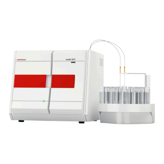
Endress+Hauser analytikjena multi N/C pharma HT Manuals
Manuals and User Guides for Endress+Hauser analytikjena multi N/C pharma HT. We have
2
Endress+Hauser analytikjena multi N/C pharma HT manuals available for free PDF download: Operating Manual
Endress+Hauser analytikjena multi N/C pharma HT Operating Manual (128 pages)
Brand:
Endress+Hauser
| Category:
Measuring Instruments
| Size: 18 MB
Table of Contents
Table of Contents
3
Basic Information
7
User Manual Notes
7
Analyzer Area of Application
7
Intended Use
8
Warranty and Liability
8
Technical Data
10
Safety Instructions
12
Standards and Directives
12
Symbols and Signal Words Used
13
Safety Markings on the Analyzer
13
Technical Condition
14
Requirements for the Operating Personnel
14
Safety Instructions, Transport and Installation
15
Safety Instructions - Operation
16
General
16
Safety Instructions - Protection against Explosion and Fire
16
Safety Instructions - Electrical Equipment
16
Safety Instructions for Compressed Gas Containers and Systems
17
Handling of Auxiliary and Operating Materials11
17
Safety Instructions - Service and Repair
18
Behavior During Emergencies
19
Technical Description
20
System Design
20
Fig. 1 Front View (Doors Open)
20
Components for Sample Preparation
21
Fig. 2 Lateral View Left (Side Wall Removed)
21
Fig. 3 Syringe Pump with 2 Port Valve
21
Hose System
22
4.1.2.1 Hose Diagram
22
Fig. 4 Hose Diagram
22
4.1.2.2 Connection Method
23
4.1.2.3 Components for Flow Adjustment
23
Fig. 5 Different FAST Connector Designs
23
Fig. 6 Fingertight Screw Connection
23
4.1.2.4 Hose Pumps
24
Fig. 7
24
Fig. 7 Needle Valve to Adjust the NPOC Purging
24
Fig. 8 Condensate Pump
24
Combustion System
25
Fig. 9 Phosphoric Acid Pump
25
Fig. 10 Combustion Furnace (See Arrow)
25
Components for Measuring Gas Drying and Cleaning
26
4.1.4.1 Condensation Coil
26
4.1.4.2 TIC Condensation Module
26
Fig. 11
26
Fig. 11 Condensation Coil
26
4.1.4.3 Water Traps
27
Fig. 12 TIC Condensation Module
27
Fig. 13 Water Traps
27
4.1.4.4 Halogen Trap
28
Detectors
28
4.1.5.1 NDIR Detector
28
Fig. 14 Halogen Trap
28
Chemiluminescence Detector CLD (Optional)23
29
Indicator and Control Elements, Connections
29
Fig. 15 LED to Indicate Readiness for Operation
29
Fig. 16 LED Strip (Right Door Open)
29
Accessories
30
Fig. 17 Connections on the Rear of the Device
30
Extension Options for the Analyzer
31
4.1.8.1 Sampler
31
Swab Test Module (Optional)
31
Chemiluminescence Detector CLD (Optional)25
31
Fig. 18 Swab Test Module
31
Principle of Operation
32
Fig. 19 Principle of Operation
32
Measuring Method
33
TC Analysis
33
TOC Analysis
33
TIC Analysis
34
NPOC Analysis
34
NPOC Analysis According to the NPOC Plus Method
34
TN B -Analysis
35
Catalysts
35
Calibration
35
Calibration Strategies
35
4.5.1.1 Single Point Calibration
35
4.5.1.2 Multiple Point Calibration with Constant Concentration
35
Fig
35
4.5.1.3 Multiple Point Calibration with Constant Sample Volume
36
Day Factor
36
Calibration Method in Multiwin
36
Fig
36
4.5.3.1 Tc/Npoc
37
4.5.3.2 Tic
37
TOC (Diff)
37
4.5.3.4 NPOC Plus
38
4.5.3.5 Calibration TN
38
Method Characteristics
38
Other Calculations
39
System Suitability Test (SST)
40
Fig
40
Blank Values
41
Blank Water Values
41
4.7.1.1 Blank Preparation Water Value
41
4.7.1.2 Dilution Blank Value
41
Fig
41
4.7.1.3 Eluate Blank Value
42
Fig
42
Boat Blank Value
43
Fig
43
First Commissioning
44
Site Requirements
44
Installation Conditions
44
Space Requirement
44
Fig
44
Energy Supply
45
Gas Supply
45
Unpacking and Placing the Analyzer
45
Fig
45
Connecting Add-On Devices
46
Sampler
46
AS Vario Autosampler
46
Fig
46
Fig
47
Fig. 20 Layout of the as Vario Autosampler
47
Fig. 21 Transport Lock on Autosampler as Vario
47
Fig
48
Fig. 22 Sleeve with 2 Cannulas for NPOC Measurements with Non-Parallel Purging
48
AS 21 Autosampler
49
Fig
49
Fig. 23 Hose in Fingertight Connection
49
Fig. 24 Layout of the Sampler as 21
50
Fig. 25 Connections at the Bottom of the Sampler
50
AS 10 Autosampler
52
Fig. 26 Layout of the as 10 Autosampler
53
EPA Sampler
54
Fig
54
Fig. 27 EPA Sampler
55
Fig. 28 Rear of the EPA Sampler
56
EPA Sampler
56
Transport Lock
56
Fitting the Stirring Arm to the Autosampler
57
Hose in Fingertight Connection
58
Chemiluminescence Detector (CLD)
59
CLD - Display Elements, Mains Connection and Media Connections
59
Swab Test Module
61
Technical Data
61
Structure of the Swab Test Module
61
Installing the Swab Test Module
62
Operation of the Swab Test Module
65
Maintenance of the Swab Test Module
67
Sample Boat Inserted into the Swab Test Module
67
Removal of the Swab Test Module
68
Operation
70
General Information for the Analysis Work
70
Switching on the Analyzer
70
Carrying out the Calibration
72
Preparing and Starting the Calibration
72
Calibration Window - Data of New Calibration
72
Displaying Calibration Results
74
Window Current Sample Data (with Sampler Operation)
74
Calibration Window - Data of New Calibration
75
Editing an Existing Calibration
76
Transferring Calibration Parameters to a Method
77
Disabling Individual Measured Values of a Calibration
77
Window Link to Method
78
Managing Calibration Data
79
Window Link with Method with Three Areas
79
Window Calibration Report Selection
80
Performing Measurements
81
Measurement with Manual Sample Supply
81
Measurement with Sampler
81
Maintenance and Care
83
Maintenance Intervals
83
Adjustment and Setup Tasks
85
Adjusting the as Vario Autosampler
85
Adjustment Points on the Sample Tray
86
Adjust the NPOC Purge Flow
87
Adjusting the EPA Sampler
88
Replacing the Water Traps
91
Replacing the Halogen Trap
92
Exchanging the Catalyst
93
Lifetime of the Catalyst
93
Removing the Combustion Tube
93
Filling the Combustion Tube
94
Inserting the Combustion Tube
96
Cleaning the TIC Condensate Vessel
98
Removing and Installing the Condensation Coil94
100
Removing and Cleaning the Condensation Coil94
100
Inserting the Condensation Coil
101
Cleaning and Replacing the Metering Syringe96
102
Removing and Replacing the Pump Hose
103
Replacing the Hose Connections
105
Removing and Installing the Combustion Furnace
106
Removing the Combustion Furnace
106
Fig.44
106
Fig.45
106
Hose
106
Replacing the Fingertight Connection
106
Installing the Combustion Furnace
108
Checking the System for Tightness
109
Fault Removal
110
General Information
110
Error Messages in Multiwin
111
Status Errors - Indications in the Window System State
116
Equipment Faults and Analytical Problems
118
Transport and Storage
121
Transport
121
Preparing the Analyzer for Transport
121
Fig.46
122
Fig.47
122
Components Behind the Front Door Secured for Transport
122
Combustion Furnace Removed and Loose Hose Ends Secured for Transport
122
Transport Notes
123
Preparing the Autosampler as Vario for Transport
123
Transport Lock on Autosampler as Vario
123
Moving the Analyzer in the Laboratory
124
Storage
124
Recommissioning after Transport or Storage119
125
Assembling the Analyzer after Transport or Storage
125
Connecting the Analyzer
126
Fig.49
126
Mains Connection and Gas Connections at the Multi N/C Pharma HT
126
Disposal
128
Waste Water
128
Halogen Trap
128
Catalyst
128
Analyzer
128
Advertisement
Endress+Hauser analytikjena multi N/C pharma HT Operating Manual (125 pages)
Brand:
Endress+Hauser
| Category:
Measuring Instruments
| Size: 30 MB
Table of Contents
Table of Contents
3
Basic Information
7
About this User Manual
7
Analyzer Area of Application
7
Intended Use
8
Security
9
Safety Labeling on the Device
9
Requirements for the Operating Personnel
10
Safety Instructions, Transport and Commissioning
10
Safety Instructions - Protection against Explosion and Fire
11
Summary of Safety Instructions
11
Safety Instructions: During Operation
11
Electrical System Safety Instructions
12
Safety Instructions for the Operation of Compressed Gas Containers and Compressed Gas Systems
12
Handling of Auxiliary and Operating Materials
12
Safety Instructions - Maintenance and Repair
13
Behavior During Emergencies
14
Function and Design
15
Layout
15
Figure 1 Analyzer, Front Doors Opened
15
Figure 3 Syringe Pump
16
Figure 2 Analyzer, Left Side Wall Opened
16
Sample Supply System
16
Hose System
17
Figure 4 Hose Diagram
17
Figure 5 Setting the NPOC Purge Flow
18
Figure 6 Condensate Pump
18
Figure 7 Phosphoric Acid Pump
18
Combustion System
19
Figure 8 FAST Connector
19
Figure 9 Fingertight Screw Connection
19
Figure 11 Condensation Coil
20
Figure 10 Combustion Furnace
20
Measuring Gas Drying and Cleaning
20
Figure 12 TIC Condensation Module
21
Figure 13 Water Traps
22
Figure 14 Halogen Trap
22
Detection
23
Indicator and Control Elements, Connections
24
Figure 15 Status LED
24
Figure 16 LED Strip (Right Door Open)
24
Accessories
25
Figure 17 Device Rear
25
Figure 18 Principle of Operation
26
Additional Options for the Analyzer
26
Function and Measuring Principle
26
Measuring Methods
27
TC Analysis
27
TOC Analysis
27
TIC Analysis
28
NPOC Analysis
28
DOC Analysis
28
Calibration
29
Calibration Strategies
29
Catalysts
29
TN Analysis
29
Daily Factor
30
Calibration Method
30
Method Characteristics
31
Other Calculations
32
Blank Values
33
Water Blank Values
33
Eluate Blank Value
34
Boat Blank Value
34
System Suitability Test
34
Device Layout and Space Requirements
36
Ambient Conditions
36
Installation Conditions
36
Installation and Commissioning
36
Power Supply
37
Gas Supply
37
Unpacking and Setting up the Device
37
Figure 19 Space Required for Multi N/C Pharma HT with Modules
37
Installing and Commissioning the Analyzer
38
Figure 20 Device Rear
39
Connecting Accessories
41
The as 10E and as 21Hp Autosamplers
41
Figure 21 as 10E Autosampler
41
Figure 22 as 21Hp Autosampler
42
Figure 23 Parallel Purging (Left) and Sequential Purging (Right)
43
Figure 24 Autosampler Attached to the Analyzer by Means of the Holder
43
Figure 25 Connections on the Bottom of the Autosampler
44
Figure 26 Holder
45
Figure 27 Fingertight Connection
46
Figure 28 Autosampler Adjustment Window Alignment - Sampler
47
Figure 29 Parallel Purging (Left) and Sequential Purging (Right)
47
AS Vario Autosampler
48
Figure 30 Layout of the as Vario Autosampler
49
Figure 31 Layout of the as Vario er Autosampler
50
Figure 32 Transport Lock
50
Figure 33 Sleeve with Two Canulas for Non-Parallel Purging
51
Figure 34 Fingertight Connection
52
Figure 35 Canula Flush on the as Vario er Model
52
Figure 36 Activating the Canula Flush in the Method
53
EPA Sampler
54
Figure 37 EPA Sampler Autosampler
54
Figure 38 Rear of the Autosampler
55
Figure 39 Electrical Connections
55
Figure 40 Transport Lock
56
Figure 41 Installing the Stirring Arm
56
Figure 42 Canula Position for NPOC Measurement with Parallel (Left) and Non-Parallel (Right) Purging
57
Figure 43 Fingertight Connection
57
Chemiluminescence Detector (CLD)
59
Figure 44 Chemiluminescence Detector (CLD)
59
Integrated Solids Module
60
Figure 45 Layout of the Integrated Solids Module
61
Operation
65
General Notes
65
Switching on the Analyzer
66
Switching off the Analyzer
67
Carrying out Calibration
68
Preparing and Starting Calibration
68
Figure 46 Data for New Calibration
68
Figure 47 Current Sample Data
69
Displaying the Calibration Results
70
Figure 48 Performed Calibration Data
70
Editing Calibration
71
Linking a Calibration to a Method
71
Figure 49 Linking a Calibration to a Method (3 Calibration Ranges)
72
Managing Calibration Data
73
Performing Measurements
73
Measurement with Manual Sample Feed
73
Measurement with Autosampler
74
Operating the Integrated Solids Module
75
Figure 50 Inserting the Sample Boat in the Solids Module
76
Maintenance and Care
77
Maintenance Overview
77
Adjustment and Setting
78
General Notes for Adjusting the Autosampler
78
Adjusting the as Vario Autosampler
79
Figure 51 Adjusting the Autosampler
79
Figure 52 Adjustment Points on the Sample Tray
79
Adjusting the EPA Sampler
80
Figure 53 Installing Canulas (2 Canulas for Parallel Purging Here)
81
Figure 54 Adjusting the Autosampler
81
Figure 55 Adjusting Position 1
82
Setting the NPOC Purge Flow
83
Figure 56 Grounding Conductor Connection on the Side Wall
83
Figure 57 Setting the Purge Flow
83
Figure 58 Setting the NPOC Purge Flow
84
Syringe Pump Maintenance
85
Replacing the Pump Hose
85
Replacing the Hose Connections
87
Checking the System for Leaks
88
Figure 59 FAST Connector, Angled
88
Figure 60 Replacing the Fingertight Connection
88
Removing the Combustion Tube
89
Replacing the Catalyst
89
Filling the Combustion Tube
90
Installing the Combustion Tube
92
Removing and Installing the Combustion Furnace
94
Removing the Combustion Furnace
94
Installing the Combustion Furnace
95
Cleaning the TIC Condensate Vessel
96
6.10 Condensation Coil Maintenance
97
6.11 Replacing the Water Traps
98
Figure 61 Replacing the Water Traps on the Front Side
99
Figure 62 Replacing the Water Traps on the Gas Box
100
6.12 Replacing the Halogen Trap
101
Figure 63 Replacing the Halogen Trap
102
6.13 Removing the Integrated Solids Module
103
Maintaining the Chemiluminescence Detector (CLD)
104
Figure 64 Replacing the Adsorber Cartridge
104
Troubleshooting
105
Software Error Messages
105
Status Errors
110
Device Errors
112
Preparing the Analyzer for Transport
115
Transport
115
Transport and Storage
115
Figure 65 Components Secured Behind the Front Doors for Transport
116
Preparing the as Vario Autosampler for Transport
117
Moving the Device in the Laboratory
117
Figure 66 Securing the Autosampler for Transport
117
Storage
118
Disposal
119
Specifications
120
10.1 Technical Data
120
10.2 Standards and Directives
121
Revision Overview
123
Table of Figures
124
Advertisement
Related Products
Endress+Hauser analytikjena SPECORD PLUS
Endress+Hauser analytikjena Biometra TOne
Endress+Hauser analytikjena Biometra TMS
Endress+Hauser analytikjena multi N/C UVHS
Endress+Hauser analytikjena multi N/C pharma UV
Endress+Hauser analytikjena multi EA 5100
Endress+Hauser Proline t-mass A 150
Endress+Hauser Proline Promass A 100
Endress+Hauser Proline Promass A 500 PROFINET
Endress+Hauser Proline Promass A 300 PROFINET
Endress+Hauser Categories
Measuring Instruments
Transmitter
Radar
Switch
Accessories
More Endress+Hauser Manuals
Login
Sign In
OR
Sign in with Facebook
Sign in with Google
Upload manual
Upload from disk
Upload from URL