Sign In
Upload
Manuals
Brands
Endress+Hauser Manuals
Measuring Instruments
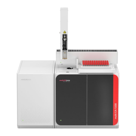
analytikjena multi EA 5100
Endress+Hauser analytikjena multi EA 5100 Manuals
Manuals and User Guides for Endress+Hauser analytikjena multi EA 5100. We have
1
Endress+Hauser analytikjena multi EA 5100 manual available for free PDF download: Service Manual
Endress+Hauser analytikjena multi EA 5100 Service Manual (224 pages)
Elementary analyzer C/N/S/Cl
Brand:
Endress+Hauser
| Category:
Measuring Instruments
| Size: 15 MB
Table of Contents
Table of Contents
3
Basic Information
9
Intended Use
9
Areas of Application for the Analysis System
12
Safety
14
General Notes
14
Safety Labeling on the Device
14
Requirements for the Operating- and Service Personnel
15
Safety Instructions for Transport and Commissioning
15
Safety Instructions for Operation
16
Professional Decontamination and Disposal of Operating Materials
20
Fig. 1 Decontamination Declaration Form
20
Danger Due to Gases in the Device
21
Danger Due to Electricity
21
ESD Protection Measures
21
Fig. 2 BA ESD 50 Operating Instruction
22
Fig. 3 Protective Equipment against Electrostatic Discharge
23
Fig. 4 Connecting the Cable to the Safety Plug
23
Fig. 5 Connecting the Grounding Cable to the Anti-Static Mat
23
Technical Data and Parameters
25
Technical Description
29
Functional Principle (Analytical)
29
Fig. 6 Overview of Components
29
Fig. 7 Vertical Mode of the Multi EA 5100
30
Fig. 8 Horizontal Mode of the Multi EA 5100
30
Block Diagram (Electrical)
32
Fig. 9 Block Diagram
32
Power Supply
33
Fig. 10 Power Supply (Diagram)
34
Fig. 11 Main Board Power Supply
35
Fig. 12 X20 Service Connector
36
Fig. 13 24 V Power Supply Unit (Control Electronics/Temperature Control)
36
Fig. 14 48 V Power Supply Unit (Furnace Heating)
37
Main Board, Firmware Controller, Temperature Controller, Circuit Diagrams
41
Fig. 15 Main Board with Interfaces
43
Fig. 16 Main Board with Leds
44
Auto-Injector
47
Fig. 17 Auto Injector
48
Fig. 18 Auto Injector Pin Assignment
48
Fig. 19 Auto Injector Pin Assignment (Main Device)
48
Fig. 20 Auto Injector AI-EA (Front View)
49
Fig. 21 Auto Injector AI-EA (Rear View)
50
Multi Matrix Sampler 5100
51
Fig. 23 MMS 5100 (Connections on Rear of the Device)
52
Fig. 24 Serial Communication of Sampler
53
Fig. 25 T-Cable for Serial Communication of Sampler
53
Abd
55
Fig. 26 ABD (Main Components)
55
Gss
58
Fig. 27 GSS Module (Front Side)
58
Fig. 28 GSS Module (Rear Side)
59
Lpg 2.0
60
Fig. 29 LPG 2.0 (Front Side)
61
Fig. 31 LPG 2.0 PCB
64
GSS/LPG Combination Module
65
Fig. 32 GSS/LPG Combination Module (Front Side)
66
Fig. 33 GSS/LPG Combination Module (Rear Side)
67
Fig. 34 GSS/LPG Combination Module PCB
69
Combustion System
70
Fig. 35 Position of Combustion Unit
70
Fig. 36 Position of Multi-Purpose Combustion Tube (with Details)
71
Fig. 37 Position of Membrane Dryer (Required for CLD and UVFD)
71
Fig. 38 Position of Thermocouple in the Furnace
72
Fig. 39 Distance of Thermocouple
72
Gas Box/Gas Supply/Gas Flows
78
Fig. 40 Hose Diagram for Horizontal Mode
78
Fig. 41 Hose Diagram for Vertical Mode
79
Fig.42 Gas Connections at the Rear of the Device
80
Fig. 43 Connections to Combustion Tube
80
Fig. 44 Gas Flow Diagram, Vertical
81
Fig. 45 Gas Flow Diagram, Horizontal
81
Fig. 46 Position of Gas Box and Gas Connections
82
Fig. 47 Measurement of Main O2 Gas Flow Rate, Vertical
83
Fig. 48Measurement of Main O2 Gas Flow Rate, Horizontal
83
Fig. 49 Measurement of Inlet Ar/O
84
Fig. 50 Measurement of Inlet Ar/O
84
Auto-Protection Valve Assembly
91
Fig. 51 Toggle Switch to Lock/Release Combustion Tube
92
Fig. 52 Membrane Dryer in the Multi EA 5100
93
Fig. 53 Valve Assembly for Measuring Gas Transfer ((Horizontal Mode)
93
Fig. 54 Connection Valve Module - Main Board
94
N-Modul 5100
96
Fig. 55 N-MODULE 5100 (Front and View from Left Without Side Wall)
98
Fig. 56 N-MODULE 5100 - Rear Panel of Device
98
S-MODULE 5100 (Basic, MPO)
100
Fig. 57 S-MODULE 5100 (Front and View from Left Without Side Wall)
101
Fig. 58 S-MODULE 5100 - Rear Panel of Device
101
Chlorine Module
104
Fig. 59 Chlorine Module (Without Measuring Cell)
105
Fig. 60 Measuring Cell "Sensitive" with Lid
106
Fig. 61 Loaded Measuring Cell "Sensitive
106
Fig. 62 Combined Electrode for "Sensitive" and "High Concentration" Measuring Cells
107
Fig. 63 Measuring Cell "High Concentration
107
Fig. 64 Measuring Cell "High Sensitive" with Lid
108
Fig. 65 Cover on "High Sensitive" Measuring Cell, Equipped with All Electrodes
108
Fig. 66 Reference Electrode and Sensor Electrode
109
Fig. 67 Platinum Electrode with Salt Bridge
110
Fig. 68 Silver Electrode (Generator Anode)
110
Fig. 69 Connections on the Rear of the Chlorine Module
111
Fig. 70 Terminal on the Internal Wall of the Chlorine Module
112
Fig. 71 Connection of Heated Gas Transfer Line to Sulfuric Acid Container
112
Fig. 72 Gas Inlet Tube with PTFE Screw Joint
113
Fig. 73 Gas Inlet in "Sensitive" Measuring Cell
113
Coulometric TS Module
118
Fig. 74 Coulometric Sulfur Detector with Measuring Cell (Without Door)
119
Fig. 75 Coulometric Sulfur Detector Without Measuring Cell
120
Fig. 76 Coulometric Measuring Cell
121
Fig. 77 Generator and Indicator Electrodes, Gas Inlet Tube
122
Fig. 78 Nox Absorber and HX Absorber
123
Fig. 79 Hose Diagram
123
Fig. 80 Rear of Coulometric Sulfur Detector
124
C Module 5100
127
Fig. 81 Basic Module with Detection and Sample Feeding Module
127
Fig. 82 Rear Panel of the Carbon Detector
128
Fig. 83 Checking the NDIR Detector (Component Test)
129
TOC Module
132
Fig. 84 TOC Detector, Door Open
133
Fig. 85 Components in Basic Module
134
Fig. 86 TOC Combustion Tube (Without Filling)
134
Fig. 87 Tube Holder for TOC Combustion Tube
135
Fig. 88 Condensation Coil
136
Fig. 89 Hose Diagram for TOC Detector
137
Fig. 90 Reverse Side of TOC Detector
138
Software and Firmware
142
Network Environment and System Requirements
142
Installation
142
Update
143
Service Software / Special Service Functions
149
Log Files
158
Fig. 91 CONFIGURATION with Open ERROR ANALYSIS Tab
158
Installation and Commissioning
160
Installation Location Requirements
160
Fig. 92 Device Layout in Horizontal Operation
162
Electrical Installation
163
Gas Installation
163
Commissioning
163
Fig. 93 Device Layout in Vertical Operation
163
Functional Test
164
Maintenance and Care
172
Maintenance Intervals
172
Maintenance Instructions
174
Wear Parts Overview (Replacement Intervals)
184
Functional Test
187
Troubleshooting
188
EA Error Message in the Software / Cause / Remedy
188
Error Diagrams
201
Fig. 94 Error 0011 - no Response to Signal
202
Fig. 95 Target Temperature Not Achieved
203
Fig. 96 Error 130 - no Communication with Cl Module
204
Fig. 97 MFC Not OK
205
Fig. 98 no TN Signal
206
Service Equipment and Testing Devices
207
Notes on Disposal
209
Annex
210
Spare Parts List (Table)
210
Consumables List (Table)
212
Fig. 22 MMS 5100
213
Drawings
215
Fig. 99 Control Electronics
215
Current Service Information
216
Fig. 100 Opened N-MODULE 5100 with New Ozone Generator (Marked in Red)
216
Fig. 101 Removing the Side Panels
217
Fig. 102 Removing Fastening Screws
217
Fig. 103 Removing the "IN" Hose
218
Fig. 104 Removing the Power Supply Connector from the PCB
218
Fig. 105 Screwing in the Screws
219
Fig. 106 Connecting the Connection Cable
219
Fig. 107 New Ozone Generator
220
Fig. 108 New Ozone Generator (View from Above)
220
Fig. 109 Rear of the N-MODULE 5100
221
Fig. 110 Readout of the Operating Hours
222
Fig. 111 Resetting the Operating Hours
222
Fig. 112 Claims Form (Example)
223
Advertisement
Advertisement
Related Products
Endress+Hauser analytikjena SPECORD PLUS
Endress+Hauser analytikjena Biometra TOne
Endress+Hauser analytikjena multi N/C pharma HT
Endress+Hauser analytikjena Biometra TMS
Endress+Hauser analytikjena multi N/C UVHS
Endress+Hauser analytikjena multi N/C pharma UV
Endress+Hauser Proline t-mass A 150
Endress+Hauser Proline Promass A 100
Endress+Hauser Proline Promass A 500 PROFINET
Endress+Hauser Proline Promass A 300 PROFINET
Endress+Hauser Categories
Measuring Instruments
Transmitter
Radar
Switch
Accessories
More Endress+Hauser Manuals
Login
Sign In
OR
Sign in with Facebook
Sign in with Google
Upload manual
Upload from disk
Upload from URL