Sign In
Upload
Manuals
Brands
Emotron Manuals
Controller
MSF 2.0
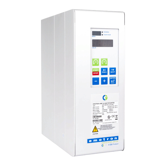
Emotron MSF 2.0 Manuals
Manuals and User Guides for Emotron MSF 2.0. We have
1
Emotron MSF 2.0 manual available for free PDF download: Instruction Manual
Emotron MSF 2.0 Instruction Manual (372 pages)
Brand:
Emotron
| Category:
Controller
| Size: 9 MB
Table of Contents
Section 1
8
Table of Contents
8
General Information
10
How to Use the Instruction Manual
10
Integrated Safety Systems
10
Safety Measures
10
Notes to the Instruction Manual
10
Type Number
10
Standards
11
Tests in Accordance with Norm en 60204 Standard
11
Transport and Packing
11
Unpacking MSF-310 and Larger Types
11
Glossary
12
Background Theory
14
Description
14
Reduced Voltage Starting
15
Other Starting Methods
17
Use of Softstarters with Torque Control
18
Mounting
20
Installation of the Softstarter in a Cabinet
20
Connections
24
Connecting Mains and Motor Cables
25
Control Connection
29
Minimum Wiring
30
Wiring Examples
30
How to Get Started
32
Checklist
32
Applications
32
Start and Stop
33
Motor Data
33
Setting the Start Command
34
Viewing the Motor Current
34
Starting
34
Applications and Functions Selection
36
Softstarter Rating According to Ac53A
36
Softstarter Rating According to Ac53B
36
The Applications Rating List
37
The Application Functions List
39
Special Conditions
41
Operation of the Softstarter
44
General Description of User Interface
44
Control Panel
44
The Keys
45
The Menu Structure
45
LED Indication
45
Control Panel Lock
46
Overview of Softstarter Operation and Parameter Set- up
47
Functional Description
48
General Settings
49
Motor Data
50
Motor Protection
51
Parameter Set Handling
56
Autoreset
57
Serial Communication
59
Operation Settings
60
Process Protection
74
I/O Settings
82
View Operation
96
Alarm List
99
Softstarter Data
100
Protection and Alarm
102
Alarm Codes
102
Alarm Actions
102
Reset
102
Alarm Overview
103
Troubleshooting
106
Fault, Cause and Solution
106
Maintenance
110
Regular Maintenance
110
Fieldbus Systems
112
External Control Panel
112
Serial Communication
112
Options
112
Terminal Clamp
113
Technical Data
114
Electrical Specifications
114
General Electrical Specifications
119
Fuses and Power Losses
120
Mechanical Specifications Including Mechanical Drawings
121
Derating at Higher Temperature
122
Environmental Conditions
122
Standards
122
Power- and Signal Connectors
123
Semi-Conductor Fuses
124
Set-Up Menu List
126
Section 2
141
Description
143
General Information
143
Introduction
143
Users
143
Delivery and Unpacking
144
Safety
144
General
145
Modbus RTU
145
Framing
148
Functions
151
Errors, Exception Codes
162
Installation
165
Installation on MSF-017 to MSF-145
165
Installation of MSF-170 to MSF-1400
167
RS485 Multipoint Network
168
RS232 Point to Point Network
170
Communication Parameters
173
Set-Up Communication Parameters
173
Serial Communication as Control Source
176
Coil Status List
177
Parameter List
177
Input Register List
178
Input Status List
178
Holding Register List
182
Parameter Description
186
Performance
187
CRC Generation
189
Generation in Steps
189
Section 3
237
Designated Use
238
Installation, Commissioning and Operation
238
Operational and Process Safety
238
Safety Instructions
238
Notes on Safety Conventions and Icons
239
Device Designation
240
Identification
240
CE Mark, Declaration of Conformity
241
Incoming Acceptance and Storage
241
Installation
241
Registered Trademarks
241
Scope of Delivery
241
Installation Conditions
242
Installation Instructions
243
Post-Installation Check
246
Connecting the Device
247
Wiring
247
Measuring Unit Electrical Connection
250
Post-Connection Check
250
Exterior Cleaning
251
Maintenance
251
Operation
251
Accessories
252
Additional Weight for FMX167 with an Outer Diameter of 22 MM and 29 MM
252
Mounting Clamp
252
Terminal Box
252
Extension Cable Mounting Screw
253
Terminals
253
Testing Adapter for Waterpilot with an Outer Diameter of 22 MM and 29 MM
253
TMT181 Temperature Head Transmitter (4 to 20 Ma)
253
Cable Marking
254
Troubleshooting
254
Troubleshooting Specific to TMT181 Temperature Head Transmitter
254
Troubleshooting Specific to Waterpilot FMX167 with Optional Pt100
254
Disposal
255
Return
255
Spare Parts
255
Section 4
261
About this Document
263
Function
263
Symbolism Used
263
Target Group
263
Appropriate Use
264
Authorised Personnel
264
For Your Safety
264
General Safety Instructions
264
Warning about Misuse
264
CE Conformity
265
Fulfilling NAMUR Recommendations
265
Safety Approval Markings and Safety Tips
265
Environmental Instructions
266
Safety Instructions for Ex Areas
266
Configuration
267
Product Description
267
Operation
268
Principle of Operation
268
Packaging, Transport and Storage
269
General Instructions
270
Mounting
270
Mounting Steps
271
Connecting to Power Supply
272
Preparing the Connection
272
Connection Procedure
274
Wiring Plan
275
Setup Steps with VEGADIS 12
277
Setup up
277
Setup with Pactware
280
Connect the PC with VEGACONNECT 4
281
Parameter Adjustment with AMS™ and PDM
282
Parameter Adjustment with Pactware
282
Saving the Parameter Adjustment Data
282
Vegabar 74 - 4
282
Fault Clearance
283
Maintenance and Fault Rectification
283
Instrument Repair
284
Dismounting
285
Dismounting Steps
285
Disposal
285
Supplement
286
Technical Data
286
Dimensions
293
Industrial Property Rights
299
Trademark
299
Vegabar 74 - 4
299
Content 1 about this Document
305
About this Document
307
Function
307
Symbolism Used
307
Target Group
307
Appropriate Use
308
Authorised Personnel
308
CE Conformity
308
For Your Safety
308
General Safety Instructions
308
Safety Approval Markings and Safety Tips
308
Warning about Misuse
308
Environmental Instructions
309
Safety Instructions for Ex Areas
309
Configuration
310
Product Description
310
Operation
311
Principle of Operation
311
Packaging, Transport and Storage
312
General Instructions
313
Mounting
313
Mounting Instructions
313
Connecting to Power Supply
314
Preparing the Connection
314
Connection Procedure
315
Wiring Plan
316
Adjustment of the Pressure Transmitter
319
Set up
319
Indication Scaling
321
Maintenance and Fault Rectification
323
Remove Interferences
323
Instrument Repair
324
Dismounting
326
Dismounting Steps
326
Disposal
326
Advertisement
Advertisement
Related Products
Emotron EL-FI M20
Emotron FLD48-003-54
Emotron FLD48-004-54
Emotron FLD48-006-54
Emotron FLD48-008-54
Emotron FLD48-010-54
Emotron FLD48-013-54
Emotron FLD48-018-54
Emotron FLD48-025-20
Emotron FLD48-026-54
Emotron Categories
DC Drives
Controller
Inverter
Control Unit
Industrial Electrical
More Emotron Manuals
Login
Sign In
OR
Sign in with Facebook
Sign in with Google
Upload manual
Upload from disk
Upload from URL