Sign In
Upload
Manuals
Brands
Emerson Manuals
Oxygen Equipment
World Class 3000
Emerson World Class 3000 Manuals
Manuals and User Guides for Emerson World Class 3000. We have
2
Emerson World Class 3000 manuals available for free PDF download: Instruction Manual, Instruction Bulletin
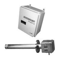
Emerson World Class 3000 Instruction Manual (184 pages)
Oxygen Analyzer with IFT 3000 Intelligent Field Transmitter
Brand:
Emerson
| Category:
Measuring Instruments
| Size: 3 MB
Table of Contents
Effective May, 2005 Rev
6
Revised Figure
13
Table of Contents
15
Definitions
19
Preface
19
Safety Instructions
20
Glossary of Terms
21
Figure 1. Complete World Class 3000 System
23
Quick Start Guide
24
Figure 2. Wiring Layout for World Class 3000 System Without HPS or MPS
26
Component Checklist of Typical System (Package Contents)
29
Description and Specifications
29
Figure 1-1. Typical System Package
29
Appendix J
30
System Overview
30
Figure 1-2. Typical System Installation
33
Figure 1-3. World Class 3000 Typical Application with Intelligent Field Transmitters
34
Installation
37
Oxygen Analyzer (Probe) Installation
37
Figure 2-1. Probe Installation
38
Figure 2-2. Orienting the Optional Vee Deflector
43
Figure 2-3. Air Set, Plant Air Connection
44
Figure 2-4. Outline of Intelligent Field Transmitter
45
Intelligent Field Transmitter (IFT) Installation
45
Figure 2-5. Power Supply Board Jumper Configuration
46
Figure 2-6. IFT Power Supply Board Jumpers
47
Figure 2-7. Wiring Layout for IFT Systems Without HPS
48
Figure 2-8. Microprocessor Board Jumper Configuration
49
Heater Power Supply Installation
49
Figure 2-9. IFT Microprocessor Board
50
Figure 2-10. Interconnect Board Jumper Configuration
51
Figure 2-11. IFT Interconnect Board Output Connections
51
Figure 2-12. Outline of Heater Power Supply
52
Figure 2-13. Wiring Layout for Complete IFT 3000 System with HPS
53
Figure 2-14. Heater Power Supply Wiring Connections
55
Figure 2-17. MPS Module
57
Figure 2-18. MPS Gas Connections
58
Figure 2-19. MPS Probe Wiring
59
Configuring the Analog Output
61
Overview
61
Setting Calibration Parameters
61
Setup
61
Configuring Efficiency Calculations
62
Configuring the Relay Outputs
62
Setting the Oalarm Setpoints
62
Analog Output Calibration
63
Calibration
63
System Calibration
63
Figure 4-1. Typical Calibration Setup
66
Figure 4-2. Portable Rosemount Analytical Oxygen Calibration Gas Kit
67
Figure 4-3. Typical Portable Calibration Setup
68
Figure 4-4. Typical Automatic Calibration System
69
Table 4-1. Automatic Calibration Parameters
70
Figure 5-1. Deluxe Version IFT Displays and Controls
74
Help Key
75
Main Menu
75
Probe Data Sub-Menu
75
Quick Reference Chart
75
Status Line
75
Table 5-1. Sample HELP Messages
75
Table 5-2. MAIN Menu
75
Calibrate Osub-Menu
76
Setup Sub-Menu
76
Table 5-3. PROBE DATA Sub-Menu
76
Figure 5-2. Quick Reference Chart
77
Sub-Menu
83
Table 5-4. CALIBRATE O
83
Table 5-5. SETUP Sub-Menu
84
Table 5-6. Efficiency Constants
86
Appendix E
87
Overview
87
Special Troubleshooting Notes
87
System Troubleshooting
87
Troubleshooting
87
Appendix D
88
Table 6-1. IFT Status Codes
88
Heater Problem
89
Table 6-2. Heater Troubleshooting
89
Cell Problem
91
Table 6-3. Cell Troubleshooting
91
IFT Problem
93
Table 6-4. IFT Troubleshooting
93
MPS Problem
94
Table 6-5. MPS Troubleshooting
94
Performance Problem (Process Response Is Suspect)
95
Table 6-6. Performance Problem Troubleshooting
95
Return of Material
97
Appendix A
99
Appendix B
99
Appendices
125
General User Interface (Gui) Operation
73
Overview
73
Deluxe Version IFT Displays and Controls
74
Figure 2-15. Jumper Selection Label
56
Figure 2-16. Jumpers on HPS Mother Board
56
Multiprobe Calibration Gas Sequencer Installation
57
Replacement Parts
125
Index
181
Advertisement
Emerson World Class 3000 Instruction Bulletin (76 pages)
Oxygen Analyzer with HPS Heater Power Supply Field Module (for use with Existing Signal Conditioning Electronics)
Brand:
Emerson
| Category:
Oxygen Equipment
| Size: 1.85 MB
Table of Contents
Table of Contents
5
Definitions
7
Preface
7
Safety Instructions
8
Component Checklist of Typical System (Package Contents)
9
Description
9
Figure 1-1. Typical System Package
9
Overview
9
Figure 1-2. Typical System Installation
11
Figure 1-3. Typical System Wiring
12
Installation
13
Oxygen Analyzer (Probe) Installation
13
Figure 2-1. Probe Installation
14
Figure 2-2. Orienting the Optional Vee Deflector
19
Figure 2-3. Outline of Heater Power Supply
19
Figure 2-4. Electrical Installation of Heater Power Supply
20
Figure 2-5. Heater Power Supply Wiring Connections
21
Heater Power Supply Installation
21
Figure 2-6. Jumper Selection Label
22
Figure 2-7. Jumpers on HPS Mother Board
23
Figure 3-1. Temperature Controller Card Calibration Points
25
Models 218, 225, and 132 (Analog) Electronics Setup
25
Overview
25
Setup
25
Figure 3-2. Main PCB (Model 218A) EPROM Replacement
26
Model 218A Electronics Setup
26
Figure 3-3. Main PCB (Model TC200) EPROM Replacement
27
Model TC200 VERITRIM Electronics Setup
27
Figure 3-4. Main PCB (Model 132) EPROM Replacement
28
Model 132 Digital Electronics Setup
28
Overview
29
System Troubleshooting
29
Troubleshooting
29
Return of Material
31
Appendices
33
Replacement Parts
71
Index
73
Advertisement
Related Products
Emerson Clarity II
Emerson Clarkson series
Emerson Clarkson KGF
Emerson Clarkson KGF-HP
EMERSON CLC320EM2F
Emerson CL900
Emerson CL125
Emerson Bettis CL-15
Emerson Bettis CL-25
Emerson CLOSETMAID Mini Offset Organizer
Emerson Categories
Controller
Control Unit
Transmitter
Measuring Instruments
Fan
More Emerson Manuals
Login
Sign In
OR
Sign in with Facebook
Sign in with Google
Upload manual
Upload from disk
Upload from URL