Sign In
Upload
Manuals
Brands
Emerson Manuals
Measuring Instruments
Micro Motion CDM100M A Series
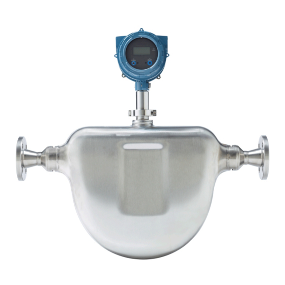
Emerson Micro Motion CDM100M A Series Manuals
Manuals and User Guides for Emerson Micro Motion CDM100M A Series. We have
1
Emerson Micro Motion CDM100M A Series manual available for free PDF download: Configuration And Use Manual
Emerson Micro Motion CDM100M A Series Configuration And Use Manual (238 pages)
Compact Density Meters
Brand:
Emerson
| Category:
Measuring Instruments
| Size: 5.21 MB
Table of Contents
Table of Contents
3
Getting Started
9
Chapter 1 Before You Begin
11
About this Manual
11
Model Codes and Device Types
11
Communications Tools and Protocols
12
Additional Documentation and Resources
13
Chapter 2 Quick Start
15
Power up the Transmitter
15
Check Meter Status
15
Make a Startup Connection to the Transmitter
16
Zero the Meter
17
Zero the Meter Using the Display
17
Zero the Meter Using Prolink III
18
Zero the Meter Using the Field Communicator
19
Part II Configuration and Commissioning
21
Configure Process Measurement
21
Chapter 3 Introduction to Configuration and Commissioning
23
Default Values
23
CDM Default Values
23
Enable Access to the Off-Line Menu of the Display
24
Disable HART Security
25
Set the HART Lock
27
Restore the Factory Configuration
27
Chapter 4 Configure Process Measurement
29
Verify the Calibration Factors
29
Calibration Factors
30
Configure Line Density Measurement
31
Configure Density Measurement Unit
31
Label
31
Configure Density Damping
33
Configure Density Cutoff
34
Configure Two-Phase Flow Parameters
34
Configure Temperature Measurement
36
Configure Temperature Measurement Unit
36
Configure Temperature Damping
37
Unit Description Display Prolink
37
Configure Temperature Input
38
Configure the Pressure Input
41
Configure the Pressure Input Using Prolink III
41
Configure the Pressure Input Using the Field Communicator
43
Options for Pressure Measurement Unit
44
4.5 Set up the Api Referral Application
45
Set up the API Referral Application
45
Set up the API Referral Application Using Prolink III
45
Set up the API Referral Application Using the Field Communicator
50
Field Communicator
50
Referral Application
50
The Concentration Measurement Application and the API Referral Application Cannot
51
Be Enabled Simultaneously
51
Prerequisites
51
To be Used in Referred Density Calculations
51
Set up Concentration Measurement
58
Preparing to Set up Concentration Measurement
58
4.6.2 Set up Concentration Measurement Using Prolink III
59
Set up Concentration Measurement Using Prolink III
59
Set Reference Temperature Values for Specific Gravity Using Prolink
61
Set up Temperature Data for Concentration Measurement Using Prolink
62
Modify Matrix Names and Labels Using Prolink III
64
Modify Operational Parameters for Concentration Measurement Using Prolink
64
Enable the Concentration Measurement Application Using
66
Select the Active Concentration Matrix Using Prolink III
66
Set up Concentration Measurement Using the Field Communicator
66
Using Equations to Calculate Specific Gravity, °Baumé, °Brix, °Plato, and °Twaddell
71
Matrix Switching
72
Configure Velocity Measurement
74
Set up Flow Monitoring
74
Prolink III
75
Configure Volume Flow Rate Measurement
76
Configure Flow Direction
78
Configure Flow Damping
82
Chapter 5 Configure Device Options and Preferences
83
Configure the Transmitter Display
83
Configure the Language Used for the Display
83
Configure the Number of Decimal Places (Precision) Shown on the Display
84
Configure the Process Variables and Diagnostic Variables Shown on the Display
84
Configure the Refresh Rate of Data Shown on the Display
85
Enable or Disable Automatic Scrolling through the Display Variables
85
Enable or Disable the Acknowledge All Alerts Display Command
86
Configure Security for the Display Menus
87
Configure Alert Handling
88
Configure Fault Timeout
88
Configure Alert Severity
89
Configure Informational Parameters
91
Chapter 6 Integrate the Meter with the Control System
93
Configure Channel B
93
Configure the Ma Output
94
Configure Ma Output Process Variable
94
Configure Lower Range Value (LRV) and Upper Range Value (URV)
96
Configure Added Damping
97
Configure Ma Output Fault Action and Ma Output Fault Level
99
Configure the Discrete Output
100
Configure Discrete Output Source
100
Configure Discrete Output Polarity
101
Configure Discrete Output Fault Action
102
Configure an Enhanced Event
103
Configure Hart/Bell 202 Communications
104
Configure Basic HART Parameters
104
Configure HART Variables (PV, SV, TV, QV)
105
Configure Burst Communications
107
Configure Modbus Communications
111
Configure Digital Communications Fault Action
113
Options for Digital Communications Fault Action
113
Chapter 7 Complete the Configuration
115
Test or Tune the System Using Sensor Simulation
115
Back up Transmitter Configuration
115
Enable HART Security
116
Part III Operations, Maintenance, and Troubleshooting
119
Chapter 8 Transmitter Operation
121
Record the Process Variables
121
View Process Variables and Diagnostic Variables
121
View Process Variables and Other Data Using Prolink III
122
View Process Variables Using the Display
122
View Process Variables Using the Field Communicator
123
View and Acknowledge Status Alerts
123
View and Acknowledge Alerts Using the Display
123
View and Acknowledge Alerts Using Prolink III
125
Alert Data in Transmitter Memory
126
View Alerts Using the Field Communicator
126
Chapter 9 Measurement Support
129
Perform the Inline Calibration Check Procedure
129
Perform the Inline Calibration Check Using Prolink III
130
Perform the Inline Calibration Check Using the Field Communicator
131
Perform the Known Density Verification Procedure
131
Perform the Known Density Verification Procedure Using the Display
132
Perform the Known Density Verification Procedure Using Prolink III
133
Perform the Known Density Verification Procedure Using the Field Communicator
133
Adjust Density Measurement with Density Offset or Density Meter Factor
134
Perform Density Offset Calibration
135
Perform Density Offset Calibration Using the Display
136
Perform Density Offset Calibration Using Prolink III
137
Perform Density Offset Calibration Using the Field Communicator
137
Adjust Temperature Measurement with Temperature Offset
138
Adjust Concentration Measurement with Trim Offset
139
Adjust Concentration Measurement with Trim Slope and Trim Offset
140
Set up User-Defined Calculations
142
Equations Used in User-Defined Calculations
144
Measurement Units Used in User-Defined Calculations
144
Diagnostic Density
145
Enable Calculated Diagnostic Density
146
Enable Diagnostic Input Density
146
Chapter 10 Troubleshooting
147
Quick Guide to Troubleshooting
147
Check Power Supply Wiring
148
Check Grounding
149
Perform Loop Tests
150
Perform Loop Tests Using the Display
150
Perform Loop Tests Using Prolink III
151
Perform Loop Tests Using the Field Communicator
152
Status LED States
154
Status Alerts, Causes, and Recommendations
155
Density Measurement Problems
161
Temperature Measurement Problems
162
Thermal Insulation
163
API Referral Problems
163
Concentration Measurement Problems
164
Velocity Measurement Problems
164
Milliamp Output Problems
166
Discrete Output Problems
168
Time Period Signal (TPS) Output Problems
168
Using Sensor Simulation for Troubleshooting
169
Trim Ma Outputs
169
Trim Ma Outputs Using Prolink III
169
Trim Ma Outputs Using the Field Communicator
170
Check HART Communications
170
Check Lower Range Value and Upper Range Value
172
Check Ma Output Fault Action
172
Check for Radio Frequency Interference (RFI)
173
Check Flow Direction
173
Check the Cutoffs
173
Check for Two-Phase Flow (Slug Flow)
174
Check the Drive Gain
174
Excessive or Erratic Drive Gain
175
Collect Drive Gain Data
176
Check the Pickoff Voltage
176
Collect Pickoff Voltage Data
177
Check for Internal Electrical Problems
177
Locate a Device Using the HART 7 Squawk Feature
178
Appendix A Calibration Certificate
179
Sample Calibration Certificates
179
Appendix B Using the Transmitter Display
183
Components of the Transmitter Interface
183
Use the Optical Switches
183
Access and Use the Display Menu System
184
Enter a Floating-Point Value Using the Display
185
Display Codes for Process Variables
188
Codes and Abbreviations Used in Display Menus
188
Appendix C Using Prolink III with the Transmitter
201
Basic Information about Prolink III
201
Connect with Prolink III
202
Connection Types Supported by Prolink III
202
Connect with Prolink III over Modbus/Rs-485
203
Connect with Prolink III over Hart/Bell 202
206
Appendix D Using the Field Communicator with the Transmitter
215
Basic Information about the Field Communicator
215
Connect with the Field Communicator
216
Appendix E Concentration Measurement Matrices, Derived Variables, and Process Variables
219
Standard Matrices for the Concentration Measurement Application
219
Concentration Measurement Matrices Available by Order
220
Derived Variables and Calculated Process Variables
222
Appendix Fmid Applications
225
Certification
225
MID Flow Computer and Power Supply Requirements
226
Flow Computer Density Calculations
226
TPS and External Input Connections to the Flow Computer
228
MID Support
228
Read Revision and Checksum Data
229
Secure the Meter
229
Switch to Unsecured Mode
232
Advertisement
Advertisement
Related Products
Emerson CSI 2140
Emerson Clarity II
Emerson Rosemount CT5100
Emerson Rosemount CT5400
Emerson Rosemount Analytical CAT 100
Emerson Rosemount CT5100 Ex
Emerson Rosemount CT5800
Emerson Nelson CM-1
Emerson Machinery Health Expert CSI 2600
Emerson Rosemount CCO 5500
Emerson Categories
Controller
Control Unit
Transmitter
Measuring Instruments
Fan
More Emerson Manuals
Login
Sign In
OR
Sign in with Facebook
Sign in with Google
Upload manual
Upload from disk
Upload from URL