Sign In
Upload
Manuals
Brands
EMC Manuals
Storage
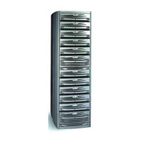
CLARiiON CX700
EMC CLARiiON CX700 Manuals
Manuals and User Guides for EMC CLARiiON CX700. We have
2
EMC CLARiiON CX700 manuals available for free PDF download: Planning Manual, Hardware Reference Manual
EMC CLARiiON CX700 Planning Manual (142 pages)
CONFIGURATION PLANNING GUIDE
Brand:
EMC
| Category:
Storage
| Size: 2 MB
Table of Contents
Table of Contents
3
Preface
9
Chapter 1 About CX300, CX500, Cx500I, and CX700 Storage Systems
13
Introducing CX300, CX500, Cx500I, and CX700 Storage Systems
14
CX700 Storage System
15
Fibre Channel
16
Nodes - Initiator and Target
16
Fibre Channel Storage Components
17
Switch and Point-To-Point Connections
18
A Switch Zone
19
Typical 16-Port Switch, Back View
19
Storage Component (Storage System Enclosures)
20
CX700 Storage Processor Enclosure (SPE)
20
Iscsi
22
Iscsi Storage Components
22
Nodes - Initiator and Target
22
Initiator Components
23
LAN Components
23
Switch and Point-To-Point Connections
23
Target Components
24
Types of Storage-System Installations
25
Types of Storage-System Installation
25
About Switched Shared Storage and Sans (Storage Area Networks)
26
Components of a SAN
26
Storage Groups
27
Sample Shared Storage Configuration
28
Data Access Control with Shared Storage
29
Chapter 2 RAID Types and Trade-Offs
31
Introducing RAID
32
Disk Striping
32
Mirroring
32
RAID Groups and Luns
33
Multiple Luns in a RAID Group
33
RAID Types
34
RAID 5 Group (Individual Access Array)
34
RAID 3 Group (Parallel Access Array)
35
RAID 3 Group
36
RAID 1 Mirrored Pair
37
RAID 1/0 Group (Mirrored RAID 0 Group)
38
RAID 0 Group (Nonredundant Array)
40
Individual Disk Unit
40
Hot Spare
41
How a Hot Spare Works
42
RAID Benefits and Trade-Offs
43
Performance
44
Storage Flexibility
45
Data Availability and Disk Space Usage
46
Disk Space Usage in the RAID Configuration
47
Guidelines for RAID Groups
48
Sample Applications for RAID Types
50
RAID 5 Group
50
RAID 1 Mirrored Pair
50
RAID 1/0 Group
51
Chapter 3 Storage-System Management
53
Management Ports
54
Navisphere Management Suites
56
Access Logix Software
56
Navisphere Manager
57
Navisphere Host Agent and CLI
57
Navisphere Analyzer
57
Navisphere Integrator
57
Using Navisphere Software
58
Storage Domains on the Internet
59
Navisphere Management Worksheet
60
Chapter 4 Data Replication and
63
Data Mobility Software
63
Data Replication and Data Mobility Software Overview
64
Snapview
64
What Is Snapview
65
Clones Overview and Example
65
Clones Example
66
Snapshots Overview and Example
67
Snapshot Example
68
Clone and Snapshot Trade-Offs
69
Snapview Worksheets
70
What Is Mirrorview
73
Mirrorview Example
73
Sample Mirrorview Configuration
74
Mirrorview Features and Benefits
75
Mirrorview Planning Worksheet
77
What Is Mirrorview/A
79
Mirrorview/A Example
80
Mirrorview/A Features and Benefits
81
Sample Remote Mirror Configuration
81
Mirrorview/A Planning Worksheets
84
What Is EMC SAN Copy
86
SAN Copy Example
88
Sample SAN Copy Sessions between Storage Systems
88
SAN Copy Features and Benefits
89
Implementing SAN Copy over Extended Distances
90
Sample SAN Copy over IP Configuration
91
SAN Copy Planning Worksheet
92
Chapter 5 Planning File Systems and Luns
95
Multiple Paths to Luns
96
Disk Ids
96
Sample Shared Switched Installation
96
Sample Shared Switched Storage Configuration
97
Sample Unshared Direct Installation
99
Unshared Direct Storage System
99
Planning Applications, Luns, and Storage Groups
100
Application and LUN Planning
101
LUN and Storage Group Planning Worksheet
103
LUN Details Worksheet
109
Chapter 6 Storage-System Hardware
117
Storage-System Installation Types
118
Types of Fibre Channel Storage-System Installations
118
Hardware for CX300, CX500, Cx500I, and CX700 Storage Systems
119
Storage Hardware
119
CX700 Storage System
120
Storage Processor (SP)
121
Disks
123
Planning Your Hardware Components
124
Components for Storage Systems
124
Hardware Dimensions and Requirements
125
Cabinets for Enclosures
126
Fibre Channel Data Cable and Configuration Guidelines
127
Fibre Channel Front-End Hardware Planning Worksheets
128
Chapter 7 Iscsi Configuration
133
Iscsi Initiator Port Worksheet
133
Storage System Iscsi Data Port Worksheet
134
Iscsi Initiator Port Worksheet
135
Index
137
Advertisement
EMC CLARiiON CX700 Hardware Reference Manual (114 pages)
Storage Processor Enclosure (SPE)
Brand:
EMC
| Category:
Enclosure
| Size: 2 MB
Table of Contents
Table of Contents
5
Warnings and Cautions
15
Chapter 1 About the CX700
19
Figure
20
Overview
20
CX700 with DAE2 Enclosures in a 40U Cabinet
20
CX700 Components and Features
21
Field-Replaceable Units (Frus)
21
Storage Processor Enclosure
22
CX700 Front View
23
CX700 Front View with Front Bezel Removed
23
CX700 Back View
23
CX700 Status Leds
24
CX700 Front Bezel
24
Storage Processors (Sps)
25
Location of the Sps
25
SP a and SP B Connectors
26
Power Supplies
27
SP a and SP B Status Leds
27
Location of the Power Supplies
27
Fan Module
29
Standby Power Supply (SPS)
30
Chapter 2 Setting up and Starting a CX700 System
31
Requirements
32
Installing an SPE in a Cabinet
32
Warnings and Recommendations
32
Site Requirements
33
Sample CX700 Installation (Rear View with Four Daes)
33
Cabling Requirements
34
Disk Requirements
35
CX700 Address Requirements
35
Cabling a CX700
37
Enclosure Address (EA) Switch on a DAE2
37
Making Power Connections - Ac Power Source
38
Connecting the Ac Line Cord to the Power Supply
38
Connecting the Power Cords to the Spss (DAE2 as EA 0, Loop 0)
39
Connecting Power Cords to the Spss (DAE2P as EA 0, Loop 0)
40
Making Power Connections - DC Power Source
41
Connecting Storage Processors to the Standby Power Supplies
41
Making Back-End Connections
42
Connecting DC Power Supplies to the CX700 and DAE2 SPS Ports
42
Connecting the Copper Cable to the be 0 SP Port
44
Sample CX700 and DAE Cabling - One Cabinet with Four Loops
45
Sample CX700 and DAE Cabling - Two Cabinets with Two Loops
47
Sample CX700 and DAE Cabling - Two Cabinets with Four Loops
48
Connecting Storage Processors to the External Environment
49
Connecting to a 2-Gbit Switch or HBA
50
Connecting to a 1-Gbit Switch Port or HBA
51
Connecting CX700 Sps to an External (Management) LAN
51
CX700 Powerup and Initialization
52
Power Connections (Ac System Shown)
52
CX700 Powerdown
53
Turning off the Power - Ac Systems
53
Turning off the Power - DC Systems
54
Power down each SPS (Ac Power)
54
Chapter 3 Servicing a CX700 SPE
58
Monitoring CX700 Status
58
Status Lights Visible from the Front of the CX700 SPE
58
Status LEDS, Front Bezel Removed
59
SP a and SP B Status Leds
60
Power Supply and SPS Status Leds
62
Handling Frus
63
Power Issues and Frus
63
Avoiding Electrostatic Discharge (ESD) Damage
64
Emergency Procedures (Without an ESD Kit)
65
Precautions When Removing, Installing, or Storing Frus
65
Precautions When Handling Optical Cables
66
Replacing a Fan Module
67
Removing a Fan Module
67
Removing the CX700 Front Bezel
67
Installing a Replacement Fan Module
68
Removing a Fan Module
68
Installing the Front Bezel
68
Replacing a Power Supply
69
To Remove a Power-Supply Module
69
Removing the Power Supply Ac Line Cord
69
Installing the Replacement Power Supply
70
Disconnecting DC Power Cords
70
Removing the Power Supply
70
Attaching the Line Cord and Powering on
71
Replacing a Storage Processor (SP)
71
Removing a Storage Processor
71
Installing a Replacement Storage Processor
72
Removing a Storage Processor
72
Installing a Storage Processor
73
Chapter 4 Standby Power Supply (SPS)
75
Standby Power Supply
75
About the SPS
76
SPS Installation, Front and Rear Views
78
Technical Specifications and Operating Limits
79
Appendix A Technical Specifications and Operating Limits
80
SPE Technical Specifications
80
Power Requirements
80
Sizes and Weights
81
SP Optical Cabling to Switch or Server
82
SP to DAE2/DAE2P Copper Cabling
82
SP to SPS Interface Cabling
83
SPE Standards Certification and Compliance
84
CX700 - Ac Power
84
CX700 - DC Power
85
Other Standards
85
Fibre Channel Related Standards
86
SPE Operating Limits
87
Environmental Recovery
87
SPE Shipping and Storage Requirements
88
Operational Behavior of DC Power over Voltage Range
89
SPS Technical Specifications
91
SPS to SP Interface
91
SPS Power Specifications
91
SPS Operating Limits
92
SPS Shipping and Storage Requirements
92
Dimensions and Battery Information
92
Typical SPS Self-Discharge Levels at Different Storage Temperatures
93
SPS Standards Certification/Compliance
94
1000-Watt DC SPS
95
Appendix B Customer Support
98
Overview of Detecting and Resolving Problems
98
Problem Detection and Resolution Process
98
Troubleshooting the Problem
99
Before Calling the Customer Support Center
100
Documenting the Problem
101
Reporting a New Problem
102
Sending Problem Documentation
103
Customer Support
98
Glossary
105
Power Supply
108
Index
114
Advertisement
Related Products
EMC CX700
EMC CLARiiON CX300
EMC CLARiiON CX500
EMC CX500I - Insignia CLARiiON NAS Server
EMC CelerraNS-120
EMC Celerra
EMC CX3-10
EMC CX3-20
EMC CX300i
EMC CLARiiON CX4-120
EMC Categories
Storage
Switch
Server
Enclosure
Network Hardware
More EMC Manuals
Login
Sign In
OR
Sign in with Facebook
Sign in with Google
Upload manual
Upload from disk
Upload from URL