Sign In
Upload
Manuals
Brands
Edwards Manuals
Water Pump
STP-iXA3306C
Edwards STP-iXA3306C Manuals
Manuals and User Guides for Edwards STP-iXA3306C. We have
1
Edwards STP-iXA3306C manual available for free PDF download: Manual
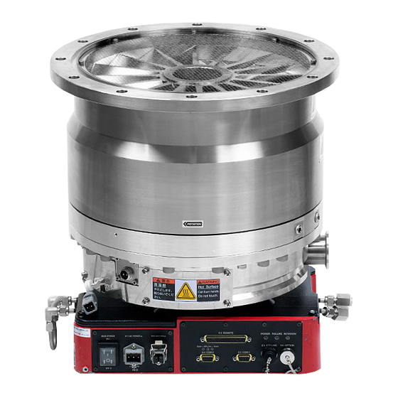
Edwards STP-iXA3306C Manual (181 pages)
STP-iXA3306 Series STP Series Turbomolecular Pumps
Brand:
Edwards
| Category:
Water Pump
| Size: 6.96 MB
Table of Contents
Declaration of Conformity
2
Table of Contents
3
Introduction
13
Scope and Definitions
13
Applied Standards
14
Limited Warranty
15
Warranty Period
15
Item Warranted
15
Disclaimer
15
Spare Parts
16
Precautions for Safe Operation of the STP Pump
17
Usable Gases
17
STP Pump Installation Warning Label
18
Hot Surface Warning Label
18
Maintenance and Inspection Precautions
18
Labels
18
Heavy Product Caution Label
19
High Voltage Device Caution Label
19
Rotation Instruction Label
19
Cross Sectional View of the STP Pump
20
Operation Principle of the STP Pump
20
STP Pump Specification
22
Technical Data
25
STP Pump Specifications
25
Maximum Gas Flow-Rate (STP-Ixa3306C)
26
Maximum Gas Flow-Rate (STP-Ixa3306Cv)
26
STP-Ixa3306B/Bv
27
Maximum Gas Flow-Rate
26
STP-Ixa3306C/CV
26
Maximum Gas Flow-Rate (STP-Ixa3306B)
27
Maximum Gas Flow-Rate (STP-Ixa3306Bv)
27
Water Cooling Use Condition
28
Control Unit
29
External Appearance of STP-Ixa3306C(V)/Ixa3306B(V)
31
External Appearance of the STP Pump
31
Label Affixing Positions
32
Installation of the Stp Pump
33
Precautions before Installation
33
Operating Environment
33
Environmental Requirements for Installation
34
Installation Area
35
Space Around the STP Pump
35
Bench
36
Insulation Test
36
Eyebolt Size
37
Example of Lifting the STP Pump
37
Unpacking
37
Unpacking the STP Pump
37
Example of Lifting the STP Pump (Horizontal Positioning)
38
Jack-Up the STP Pump
39
Control Unit Bottom Face
39
Prohibited Matter
40
STP Pump with Eyebolts
40
Pump Functions
41
Name and Function of the Control Unit
42
Configuration of the STP Pump
41
Name and Function of each Part
41
Name and Function of the Pump
41
Control Unit (Front Panel)
42
Control Unit Front Panel Functions
43
Control Unit Front Panel Functions (Continued)
44
Installation of the STP Pump to the Vacuum Equipment
45
Cleaning the Seal
46
STP Pump Installation Positions
47
How to Install the STP Pump
45
Positions of the Outlet Port on the Horizontally or Slanted Installed STP Pump
47
Secure the STP Pump
48
Tightening Torque of Bolt
48
Maximum Torque Predicted and Recommended Securing Bolt for Inlet Port Flange
49
Shape of Reduced Diameter Shank Bolts
51
Methods of Securing the STP Pump
51
Legs for Securing the Base
52
Screw Holes for Securing the Base
52
Power Cable
53
Connecting Method of the Power Cable
54
How to Connect the Power Cable
55
Precautions of Vacuum Piping
57
Vacuum Piping Method
57
Connecting the Purge Port
58
Connecting the Water Cooling Pipe
59
Positions of the Cooling Water Port
59
Attaching a Baking Heater
60
Baking Heater Installation Position
60
Installation of the TMS Unit
61
TMS Unit Specification
61
Configuration of the STP Pump with the TMS
62
Configuration of the TMS
62
TMS Heater
63
Connecting the TMS Heater Cable
63
TMS Valve
63
Connecting the Pump and TMS Valve
64
TMS Valve Connection
64
Connecting to Semiconductor Equipment
65
3.10.1 Connecting to Power
65
Emergency off Circuit (EMO Circuit)
65
Operation
67
Gas Pumping, Cooling and Baking the STP Pump
67
Gas Pumping
67
How to Introduce a Purge Gas
68
Cooling the STP Pump
68
Water-Cooling Method
68
Baking the STP Pump
69
Before Starting the STP Pump
70
Confirmation before Starting
70
Confirmation of Vacuum System
70
Powering on
71
Pump Operation
71
Input Operation Port Setting
71
Starting/Stopping the STP Pump
72
Starting/Stopping the STP Pump Using Contact Input (X2 REMOTE)
72
Pump Operation Method 1 (Contact Input)
72
Pump Operation Method 2 (Contact Input)
72
Starting/Stopping the STP Pump Using Voltage Input (X2 REMOTE) (Voltage Input)
73
Pump Operation Method 1 (Voltage Input)
73
Pump Operation Method 2 (Voltage Input)
73
Reset Operation (X2 REMOTE)
74
How to Start/Stop the STP Pump
74
Starting the STP Pump after Stopping
74
Starting the STP Pump after a Safety Function Operates
74
Powering off
74
LED Indications for each State
75
Led
75
35 "ROTATION" LED Indication
75
Parallel Port Input/Output Signal
76
Input Signal Pins
76
X2 REMOTE Connector
76
X2 REMOTE Input Signal Pins
77
X2 REMOTE Input Signal Pins (Continued)
78
X2 REMOTE Input Signal Pins (Contact Input)
79
X2 REMOTE Input Signal Pins (Voltage Input)
80
X2 REMOTE Input Signal Pins (Voltage Input) (Continued)
81
X2 REMOTE Input Signal Pins (Voltage Input)
82
Input Operation Port Setting
83
Rotation INHIBIT Signal
84
Rotation INHIBIT Signal Input
84
Second Speed Option
85
Second Speed Function
85
Output Signal Pins
86
X2 REMOTE Output Signal Pins
87
X2 REMOTE Output Signal Pins (Continued)
88
X2 REMOTE Output Signal Pins
88
Operating the TMS Unit (for Use with the TMS Unit)
90
4.10.1 before Starting
90
4.10.2 Starting/Stopping
90
4.10.3 Setting the TMS Unit Function
90
Serial Communication Protocol
91
Introduction
91
Serial Port
91
Connection and Setting up
92
Signal Connection
92
X3/X4 Pin Position
92
X3/X4 Connector (D-Sub9)
93
Connecting the RS485
94
RS485 Connections
94
Communication Parameter Setting
95
Communication Parameters
95
Input Operation Port Setting
96
Input Operation Port
96
Serial Communication Timeout Setting
97
Serial Communication Time out Setting
97
Recommended Items about Communication Cable Installation
98
Grounding Example (both Ends Grounding)
98
Grounding Example (Single Point Grounding)
98
Example of Ring Ferrite Core Installation
99
Example of Cable Installation in Metallic Duct
99
Example of Differential Signal Waveform
100
Protocol Specifications
101
General Description
101
PC to SIM Communication
101
Standard Transmission Frame
102
Transmission Control Characters
102
(In the RS232/RS485 Single Point Connection)
103
Query Command
104
(In the RS232/RS485 Single Point Connection)
104
Transmission Data Format
105
Frame Control (Checksum)
106
Error Control
106
Transmission Frame in the RS485 Multi-Point Connection
106
Control Command in the RS485 Multi-Point Connection
108
5.3.10 Query Command in the RS485 Multi-Point Connection
109
5.3.11 Broadcasting Command in the RS485 Multi-Point Connection
110
Pump Operation Commands
110
5.3.12 Application Note
111
Block Diagram of Communication Process Example
111
Example of Answer Resending Process
112
Example of Response When the Command Is Sent Continuously
112
Example of Command Sending During Answer Data Reply
112
Example of Communication Cycle Process
113
Example of Command Sending Process
114
Example of Answer Receiving Process
114
Command Specifications
115
Command List
115
Readmeas
116
Command
116
Readfailmess
117
Pump Operation Commands
117
Error Message Values
119
Error Message Values (Continued)
120
Readmodfonct
121
Pump Operation Mode
122
Readversion
123
Readcounters
124
Readsetpoint
125
Readmotortemp
125
5.4.10 Readstatus
126
5.4.11 Readevents
127
Remote Mode
127
5.4.12 Setspeedsetpoint
128
5.4.13 Readspeedsetpoint
129
5.4.14 Readmodfonctwithwarning
130
Warning Value Bit Assign
131
5.4.15 Readmeasvalue
133
5.4.16 Readoptionfunc
135
Parameter Setting Value
136
5.4.17 Setoptionfunc
138
5.4.18 Readcondition
140
5.4.19 Readeventswithtime
142
5.4.20 Setoptions
146
Option Function Number and Parameter List
146
Second Speed Option Setting
146
5.4.20.2 Second Speed Selection
147
5.4.21 Readoptions
148
5.4.21.1 Second Speed Function Setting
148
Option Function Number and Parameter List
148
Second Speed Select
149
Stp-Link and Display Unit
151
STP-Link
151
Functions of STP-Link
151
Display Unit
152
Display Unit Idt-001
152
Safety Functions
153
Power Failure
153
Operation after a Power Recovery
154
States of Leds and X2 REMOTE Output Signals at Power Failure
154
Abnormal State of Magnetic Bearing (Disturbance)
155
Excessive Vibration (Disturbance)
155
Motor Driver Overload (DRV Overload)
155
Overheating Inside the STP Pump (MOTOR Overheat)
155
Overheating Inside the Control Unit (CNT Overheat)
155
Overspeed
156
Abnormality/Error in the TMS Unit (for Use with the TMS Unit)
156
WARNING" Function
157
WARNING Function
157
WARNING Output
158
Contents of WARNING Function
159
First Damage Limit
159
Second Damage Limit
159
Pump Run Time over
159
Pump Overload
160
Imbalance
160
Default Setting of WARNING Function
161
Factory Setting and Variable Range
161
WARNING Function Setting
161
Error List
162
Troubleshooting Immediately after Failure Occurs
162
After Power Failure
162
After Other Abnormality/Error
162
Priority of Failure Signal
163
Failure Output
163
Troubleshooting
163
Indication of "FAILURE" LED (Red)
163
Error List (Continued)
165
Error List (Continued)
166
Error List (Continued)
167
Error List (Continued)
168
Error List (Continued)
169
Indication of "FAILURE" LED (Green)
170
No Indication of the "FAILURE" LED
170
Troubleshooting with no Indication of the "FAILURE" LED
170
Maintenance and Inspection
171
Cleaning
172
Inspecting the Deposit
172
Maintenance
173
Recommended Overhaul Intervals
173
Standard Replacement Parts
173
Recommended Maintenance Intervals for Main Parts
174
Transporting for Repair or Overhaul
175
Storage and Disposal
177
Storage of the STP Pump
177
Disposal
178
Service, Spares and Accessories
179
Introduction
179
Service
179
Spares
179
Accessories
180
Advertisement
Advertisement
Related Products
Edwards STP-iXA3306B
Edwards STP-iXA3306CV
Edwards STP-iXA3306BV
Edwards STP-iXA3307 Series
Edwards STP-iXA3307-HV Series
Edwards STP-iXA2205C
Edwards STP-iXA2205CP
Edwards STP-iXA2205CV
Edwards STP-iXA2205CPV
Edwards STP-iXA2205CIP
Edwards Categories
Water Pump
Control Unit
Measuring Instruments
Controller
Medical Equipment
More Edwards Manuals
Login
Sign In
OR
Sign in with Facebook
Sign in with Google
Upload manual
Upload from disk
Upload from URL