Sign In
Upload
Manuals
Brands
Eaton Manuals
Inverter
Power Xpert Solar 1500
User Manuals: Eaton Power Xpert Solar 1500 Inverter
Manuals and User Guides for Eaton Power Xpert Solar 1500 Inverter. We have
1
Eaton Power Xpert Solar 1500 Inverter manual available for free PDF download: User Manua
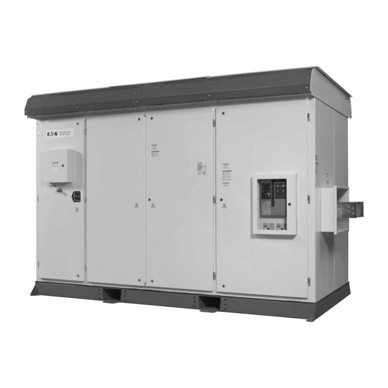
Eaton Power Xpert Solar 1500 User Manua (90 pages)
Utility-Scale Photovoltaic Inverter
Brand:
Eaton
| Category:
Inverter
| Size: 2 MB
Table of Contents
Table of Contents
6
Definitions, Safety, and Limitations
11
Read These Instructions FIRST
11
Save These Instructions
11
Definitions and Symbols
11
Table 1. Word Meanings: "Shall, " "May, " "Must, " and "Should
11
Safety Procedures
12
Figure 1. Symbols and Descriptions
12
Limitations
14
Figure 2. DANGER-WARNING-CAUTION-NOTICE
14
Product Description
15
Product Information and Labeling
15
Figure 3. Power Xpert Solar Inverter Rating Label (Typical)
15
Inverter Overview and Highlights
16
Figure 4. Power Xpert Solar 1500/1670 Kw Inverter Diagram
16
Table 2. Standard Inverter Features
17
Major Components and Functionality
18
Figure 5. Major Components Diagram: Inverter and Step-Up Transformer
18
Figure 6. Power Xpert Solar Inverter with Step-Up Transformer
18
Table 3. DC Input Fuse Re-Combiner Options: Power Xpert Solar 1500/1670 Kw Inverter
20
Figure 7. Power Xpert Solar: Inverter Power Module and Power Stacks
21
Figure 8. Schematic of the Ventilation-Principle
22
Installation Instructions
23
Delivery Inspection
23
Unloading and Moving Procedure
23
Figure 9. Mounting of Lifting Brackets
23
Figure 10. Mounting of Cover Plates
23
Table 4. Mounting
23
Dimensions and Weight
24
Figure 11. Inverter Transport by Lift Truck
24
Figure 12. Inverter Transport by Crane
24
Clearance Requirements
25
Figure 13. Inverter Cabinet Locations
25
Table 5. Inverter Minimum and Required Clearances
25
Ventilation
26
Anchoring Requirements-Concrete Pad and Seismic
26
Figure 14. Anchoring Requirements
26
DC Input Fuse Options-Re-Combiner
27
Table 6. Re-Combiner Input Options: Power Xpert Solar 1500/1670 Kw Inverter
27
Figure 15. Inverter Conductor Entry-Routing
28
Figure 16. Inverter and Transformer Conductor Entry Locations
28
Electrical Connections
29
Figure 17. Electrical Connections, Power Xpert Solar 1500/1670 Kw Inverter
30
DC Circuit Connection
31
Figure 18. PV Conductor Terminations (Typical)-Positive and Negative Connections
31
Table 7 . Fasteners and Sequence for Conductor Termination
31
Figure 19. Typical Mounting with MV Transformer
32
Inverter AC Connection
32
Neutral and Equipment Ground
33
Phase Rotation
33
Figure 20. Phase Locations
34
Figure 21. AC Output Phase Connections: Throat Connection Details
34
Table 8. 3-Wire Connection-Inverter Point-Of-Common Coupling Interface
34
Grounding Conductors
35
Grounding Electrode Terminal and Conductor
35
Figure 22. DC Section: 24 Input-Circuit Options, Illustrated PV Input Connections
36
Figure 23. DC Section Grounding Bus and Grounding Electrode Terminal
36
Grounding
36
Positive-Ground Photovoltaic Configuration
36
Figure 24. AC Section Equipment Grounding Bus
37
Figure 25. Accessory Power Location
37
Figure 26. Inverter AC Cabinet Section
38
Inverter Operation
39
Pre-Commission Check
39
Energize and Operation Procedure: Automatic Operation
40
De-Energize Procedure
43
Interactive Menu
44
Figure 27. HMI Menu Display Navigation
45
Operational States
46
Maintenance
49
Maintenance Schedule
50
Table 9. 30-Day, 6-Month and Annual Inspection and Maintenance
50
Troubleshooting
53
Identifying Inverter Faults and Warnings
53
Inverter Response to Faults and Warnings
53
Table 10. Fault and Warning Types: Actions and Resolution
54
Figure 28. Power Xpert Solar Machine-State Transition Diagram
56
Table 11. Critical Faults: CRITICAL FAULTS
56
Table 12. Non-Critical Faults: FAULT
58
Table 13. Warnings that Become Faults: WARNING R FAULT
59
Table 14. Warnings that Cannot Become Faults: FAULT R
64
Table 16. Inverter Inhibit Status: INHIBIT
65
Table 15. Alerts that Signal Inverter Service Is Required: NOTIFY
65
Troubleshooting Ground-Faults
66
Figure 29. the GFDI Connection Points
69
Table 17 . Power Xpert Solar Electrical, Mechanical and Equipment Specifications
75
Table 18. Grid-Tie Settings: Protection Relay
77
Figure 30. Flex Bus Kit: 84-37413-1
79
Figure 31. Example of Available Step-Up Transformer Monitoring
80
Table 19. Step-Up Transformer Sensor Signals
80
Table 20. DC Section Electrical Connection Torque Values
81
Table 21. AC Section Electrical Connection Torque Values
81
Table 22. Ground Connections
81
Table 23. Inverter Fuses
82
Figure 32. Enclosure Lifting Instructions
85
Figure 33. Location of CB4 in the Electrical Path
86
Table 24. Maintenance Schedule Record
87
Advertisement
Advertisement
Related Products
Eaton Power Xpert Solar 1670
Eaton SPS-110/125
Eaton SPS-110/250
Eaton SPS-55/125-R
Eaton SPS-110/125-R
Eaton SPS-55/125-T
Eaton SPS-110/125-T
Eaton SR1000
Eaton SR1000T-148
Eaton SR1000T-248
Eaton Categories
UPS
Circuit breakers
Switch
Industrial Equipment
Industrial Electrical
More Eaton Manuals
Login
Sign In
OR
Sign in with Facebook
Sign in with Google
Upload manual
Upload from disk
Upload from URL