Sign In
Upload
Manuals
Brands
Eaton Manuals
UPS
Power Xpert 9395C
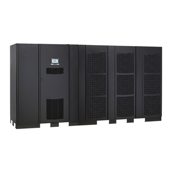
Eaton Power Xpert 9395C Manuals
Manuals and User Guides for Eaton Power Xpert 9395C. We have
1
Eaton Power Xpert 9395C manual available for free PDF download: Installation And Operation Manual
Eaton Power Xpert 9395C Installation And Operation Manual (175 pages)
Brand:
Eaton
| Category:
UPS
| Size: 13 MB
Table of Contents
Table of Contents
14
Figure 40. Normally Closed and Normally Open REPO Switch Wiring
84
Figure 41. Powerware Hot Sync CAN Bridge Card
89
Figure 42. Powerware Hot Sync CAN Bridge Card Connections
90
Figure 43. Distributed Bypass System CAN and Pull-Chain Simplified Interface Wiring
92
Figure 44. Distributed Bypass Pull-Chain Wiring with Mobs
93
Figure 45. Remote Monitor Panel II and Remote Monitor Panel II Terminal Locations
95
Figure 46. Remote Monitor Panel II, Relay Interface Module II, or Supervisory Contact Module II Wiring
96
Figure 47. J1, J2, J3, and J4 15-Pin D-Sub Connectors
98
Figure 48. Supervisory Contact Module II Terminal Location
99
Figure 49. Supervisory Contact Module II TB2
100
Figure 50. Remote Monitor Panel II Dimensions
101
Figure 51. Relay Interface Module II Dimensions
102
Figure 52. Supervisory Contact Module II Dimensions
103
Figure 53. Main Elements of the UPS System
104
Figure 54. Path of Current through the UPS in Online Mode
106
Figure 55. Path of Current through the UPS in Bypass Mode
107
Figure 56. Path of Current through the UPS in Battery Mode
108
Figure 57. One PM, Common Rectifier Feed, Common Battery, Dual-Feed Configuration
111
Figure 58. Simplified Dual-Feed UPS with Maintenance Bypass Panel
112
Figure 59. Path of Current through the Upss in Online Mode - Distributed Bypass
114
Figure 60. Path of Current through the Upss in Bypass Mode - Distributed Bypass
115
Figure 61. Path of Current through the Upss in Battery Mode - Distributed Bypass
116
Figure 62. Typical Distributed Bypass System - Continuous Static Switch, 1+1 and 2+0 Configurations
118
Figure 63. Typical Distributed Bypass System -Continuous Static Switch, 2+1 and 3+0 Configurations
119
Figure 64. Typical Distributed Bypass System -Continuous Static Switch, 3+1 and 4+0 Configurations
120
Figure 65. UPS Controls and Indicators
122
Figure 66. UPS Color Touchscreen Control Panel Location
123
Figure 67. UPS Color Touchscreen Control Panel (Typical)
124
Figure 68. Parts of the Touch Screen
126
Figure 69. Sign in or Password Request Screen
127
Figure 70. Home Screen
128
Figure 71. Meters Summary Screen
129
Figure 72. Input Meters Screen
129
Figure 73. Input Meters Detail Screen
130
Figure 74. Input Meters Select Source Screen
130
Figure 75. Bypass Meters Screen
131
Figure 76. Output Meters Screen
131
Figure 77. Output Meters Details Screen
132
Figure 78. Battery Meters Screen
132
Figure 79. System Controls Screen
133
Figure 80. Module Controls Screen
134
Figure 81. Module Control Detail Screen
134
Figure 82. Main Menu and Power Maps Screen (Online Mode)
135
Figure 83. Output Kva Screen from Home Screen
135
Figure 84. Average Efficiency Screen from Home Screen
136
Figure 85. Consumption Screen from Home Screen
136
Figure 86. Bypass Screen
137
Figure 87. UPS Module Map Screen
137
Figure 88. System Overview Screen
138
Figure 89. Typical Command Confirmation Screen (Charger Off)
138
Figure 90. System Events Screen
139
Figure 91. User Log Screen
140
Figure 92. User Log Detail Screen
140
Figure 93. Battery Log Screen
141
Figure 94. Battery Log Detail
141
Figure 95. Battery Log Summary Screen
142
Figure 96. Statistics Basic Screen
142
Figure 97. Statistics Data Detail Screen
143
Figure 98. ESS Comparison Screen
143
Figure 99. Settings Screen
144
Figure 100. Configuration Options Screen
145
Figure 101. Energy Advantage Architecture (EAA) Screen
146
Figure 102. Disable ESS Screen
146
Figure 103. High Alert Timer Screen
147
Figure 104. REPO Operation
149
Figure 105. Optional X-Slot Cards
156
Figure 106. Remote Monitor Panel II
159
Figure 107. Relay Interface Module II
161
Figure 108. Supervisory Contact Module II
162
Figure 109. ISBM Section Air Filter Locations - Continuous Static Switch
167
Figure 110. PM Section Air Filter Locations
168
Advertisement
Advertisement
Related Products
Eaton Powerware 9395 275 kVA MBM
Eaton Power Xpert 9395 550/275
Eaton Power Xpert 9395P 300 kVA
Eaton PowerXpert 9395P-600/500
Eaton PowerXpert 9395P-600/450
Eaton PowerXpert 9395P-600/400
Eaton PowerXpert 9395P-600/300
Eaton PowerXpert 9395P-600/250
Eaton Power Xpert 9395P-900 Two UPM Plus 1 FI-UPM
Eaton 9395-300
Eaton Categories
UPS
Circuit breakers
Switch
Industrial Equipment
Industrial Electrical
More Eaton Manuals
Login
Sign In
OR
Sign in with Facebook
Sign in with Google
Upload manual
Upload from disk
Upload from URL