Sign In
Upload
Manuals
Brands
Eaton Manuals
Circuit breakers
Magnum PXR
Eaton Magnum PXR Manuals
Manuals and User Guides for Eaton Magnum PXR. We have
4
Eaton Magnum PXR manuals available for free PDF download: Technical Product Manual, User Manual, Design Manual, Instruction Leaflet
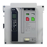
Eaton Magnum PXR User Manual (58 pages)
Low voltage power circuit breakers for use in ANSI/UL applications
Brand:
Eaton
| Category:
Circuit breakers
| Size: 11 MB
Table of Contents
Table of Contents
2
Purpose
5
Safety
5
Section 1: Introduction
5
General Information
5
Safety Features
6
Safety Practices
6
Figure 1. Family of Magnum PXR Low Voltage Power Circuit Breakers (800-6000 A)
6
Figure 2. Typical Magnum PXR Nameplate
6
Table 1 . Magnum PXR Ratings at 240, 480, 600 V
7
Table 2. Power Defense SB Ratings at 240, 480, and 600V
7
Qualified Personnel
8
Other Publications and Documentation
8
Section 2: Receiving, Handling, and Installation
8
General Information
8
Suggested Tools
8
Unpacking the Circuit Breaker
8
Figure 3. Typical Magnum PXR and PD-SB Designation Example
8
Lifting Circuit Breaker
9
Figure 4. Shipping Clamps for Drawout Circuit Breaker
9
Figure 5 . Magnum Circuit Breaker with Lifting Yoke Attached (Magnum DS Shown)
9
Circuit Breaker Inspection
10
Table 3. Basic Circuit Breaker Weights (Lifting and Support Reference Only)
10
Installing the Drawout Circuit Breaker
11
Figure 6. One Side of Drawout Circuit Breaker Properly Seated on Extension Rail
11
Figure 7. Cassette Rejection Interlock Pin Positioning/Installation
11
Figure 8. REMOVE Position
12
Figure 9. DISCONNECT Position
12
Figure 10. TEST Position
13
Figure 11. CONNECT Position
13
Levering Circuit Breaker
14
Fixed Circuit Breaker
14
Figure 12. Cassette Label Showing DISCONNECTED, TEST, and CONNECTED Position of Recessed Cover
14
Figure 13. Levering Position Indication
14
Circuit Breaker Operation
15
Section 3: Circuit Breaker Description and Operation
15
Introduction
15
Figure 14. Typical Fixed Magnum PXR Circuit Breaker
15
Figure 15 . Typical PXR Drawout Circuit Breaker Features (Front and Rear Views)
16
Figure 16 . Typical PXR Fixed Circuit Breaker Features (Front and Rear Views)
16
Figure 17 . Typical Double-Wide Standard Frame Circuit Breaker Features (Front and Rear View)
17
Figure 18 . Magnum PXR and PD-SB Drawout Circuit Breaker
18
Basic Circuit Breaker Assembly
19
Pole Units
19
Figure 19 . Typical Magnum and PD-SB Construction (Right Side View)
19
Figure 20 . Features of Magnum and PD-SB Moving Conductor Assembly
19
Figure 21. Narrow Frame (8-Finger) Moving Conductor Assembly
20
Figure 22. Standard Frame (12-Finger) Moving Conductor Assembly
20
Figure 23 . General Partial Cross-Sectional View
20
Operating Mechanism
21
Figure 24 . Typical Electrically Operated Drawout MPS Circuit Breaker with Front Cover Removed
21
Figure 25. Circuit Breaker Closing Springs Being Manually Charged (Magnum DS Shown)
21
Arc Chambers
22
Figure 26. Electrical Motor Operator to Charge Closing Spring
22
Figure 27. Cross Section of Conductor and Arc Control System
22
Figure 28. Integral Arc Runner Viewed from Top of Arc Chamber (Arc Chute Removed, Circuit Breaker Closed)
22
Electronic Tripping System
23
Figure 29. Arc Plate Assembly
23
Figure 30. Pictorial Diagram of Typical Current Sensing, Processing, and Tripping System
23
Table 4. Magnum PXR and PD-SB Trip Units
24
Figure 31. PXR 25 Programmable Trip Unit Installed in Magnum PXR Circuit Breaker
24
Figure 32. Narrow Frame Current Sensors Shown with Cover Plate Removed
25
Figure 33 . Line and Load-Side Voltage Taps for PXR Circuit Breakers
25
Accessory Devices
26
Table 5. Shunt Trip Ratings
26
Table 6. Continuous Duty Shunt Trip
26
Table 7. Spring Release Ratings
26
Figure 34. Through-The-Window Electrical Accessories
26
Figure 35. Shunt Trip with Cutoff Switch
26
Figure 36. Shunt Trip Switch Installed
26
Table 8. Undervoltage Release
27
Table 9 . Auxiliary Switch, Overcurrent Trip Switch
27
Figure 37. Spring Release with Optional Latch Switch
27
Figure 38. Undervoltage Release
27
Figure 39. Shunt Trip, Spring Release, and Undervoltage Release Installed
27
Table 10 . Compact Motor Operator
28
Figure 40. Auxiliary Switch (Form C)
28
Figure 41. Mechanical Trip Indicator with Associated Overcurrent Trip Switch
28
Figure 42. Motor Operator Kit
28
Figure 43. Motor Operator Installed in a Standard Frame Circuit Breaker
29
Figure 44. Cover Mounted Key Lock and Operations Counter
29
Figure 45. Cassette-Mounted Key Lock
29
Figure 46 . OPEN-CLOSE Pushbutton Lockable Cover Plate (Magnum DS Shown)
30
Figure 47. Typical Safety Shutters in CLOSED Position
30
Figure 48. Typical Safety Shutters in OPEN Position
30
Figure 49. Cell Switch (Drawout Position Indicator) Unmounted
30
Figure 50. Cell Switches Mounted on Cassette
30
Figure 51. Door Escutcheon and Gasket
31
Figure 52. IP55 Waterproof Cover (Magnum DS Shown)
31
Figure 53. Cassette-Mounted Two-Way Cable Interlock (Magnum DS Shown)
31
Section 4: Master Connection Diagrams
32
Secondary Contacts and Connection Diagrams
32
Figure 54 . Secondary Connector Protective Hood
32
Figure 55. Top View Secondary Connectors
32
Figure 56. Typical Cassette-Mounted Secondary Wiring
33
Figure 57. AMP Secondary Wiring Removal Tool
33
Figure 58 . Magnum PXR and PD-SB 3-Pole Wiring Diagram (PXR20/25)
34
Figure 59 . Magnum PXR and PD-SB 4-Pole Wiring Diagram (PXR20/25)
35
Figure 60 . Magnum PXR and PD-SB 6-Pole ABCABC Wiring Diagram (PXR20/25)
36
Figure 61 . Magnum PXR and PD-SB 8-Pole NABCNABC Wiring Diagram (PXR20/25)
37
Figure 62 . PXR and PD-SB 6/8 Pole Wiring Diagram (PXR20/25) for Alternate Phasing Configurations
38
Figure 63. Magnum PXR and PD-SB Accessory Wiring Diagrams (PXR 20/25)
39
Section 5: Drawout Circuit Breaker and Cassette
40
General
40
Figure 64. MPS/SPS Drawout Circuit Breaker in Cassette
40
Figure 65. MPS/SPS Drawout Circuit Breaker with Automatic Primary Disconnects
40
Figure 66. Typical Drawout Cassette Features
41
Drawout Circuit Breaker Dimensions
42
Drawout Cassette Dimensions
42
Figure 67. Typical Narrow Frame Cassette (Horizontal Terminals)
42
Figure 68. Typical Basic Cassette (Vertical Terminals)
42
Figure 69. Typical Basic Cassette (Without Stabs)
42
Figure 70 . Typical Universal Cassette, Four-Pole (Flat Terminal Pads)
42
Section 6: Fixed Circuit Breaker
43
General
43
Fixed Circuit Breaker Dimensions
43
Section 7: Importance of Maintenance
43
Safety Precautions
43
Figure 71. Fixed Narrow Frame Circuit Breaker with Available Vertical Adapter Shown
43
General Cleaning Recommendations
44
Functional Tests
44
Figure 72. CLOSED and OPEN Indicators
44
Procedure
45
Figure 73. Accessory Viewing Windows
45
Figure 74. Power Xpert Protection Manager (PXPM) Software
45
Maintenance Schedule
46
Table 11. Normal Operating Conditions
46
Table 12. Normal Maintenance Frequency
46
Table 13. Increased Frequency Conditions
46
Table 14. Altitude Rating Factors
46
Inspection Procedures
47
Table 15. Pre-Inspection Conditions
47
Figure 75. Top Rear View of Circuit Breaker with One Arc Chute Removed
47
Figure 76. Bottom View of Arc Chute
47
Table 16 . Pre-Inspection Conditions
48
Figure 77. Primary Contacts with Circuit Breaker Open (Not Used for Contact Wear Inspection)
48
Figure 78. Contact Inspection Area with Circuit Breaker Open
48
Table 17 . Pre-Inspection Conditions
49
Table 18 . Magnum and PD-SB Breaker Torque List
49
Table 19 . Greases Used on Magnum and PD-SB
49
Figure 79. Use of Contact Wear Indicator with Circuit Breaker Closed
49
Figure 80 . Magnum PXR Breaker Mechanism Lubrication
50
Figure 81 . Magnum PXR Pole Shaft Lubrication
50
Figure 82 . Magnum PXR Drawout System Lubrication (Not Applicable to Fixed-Mount Breakers)
50
Figure 83 . Magnum PXR Drawout System Lubrication
50
Figure 84 . Magnum PXR Charging Handle and Gear Lubrication
50
Figure 85 . Magnum PXR Pole Shaft and TA Spring Lubrication
50
Table 20 . Pre-Inspection Conditions
51
Table 21 . Pre-Inspection Conditions
51
Figure 86. Primary Disconnects
51
Figure 87. Breaker Secondary
51
Figure 88. Cassette Secondary
51
Table 22 . Pre-Inspection Conditions
52
Figure 89. Charged and Opened
52
Figure 90. Push to Close
52
Figure 91. Levering-In Door in Position between Disconnect and Test
53
Troubleshooting
54
Table 23. Spring Charging
54
Table 24. Contact Closing
54
Table 25. Contact Opening
55
Table 26. Levering-In/-Out (Drawout Applications Only)
55
Section 8: Renewal Parts
58
General
58
Disclaimer of Warranties and Limitation of Liability
58
Advertisement
Eaton Magnum PXR Technical Product Manual (68 pages)
Low voltage power circuit breakers
Brand:
Eaton
| Category:
Circuit breakers
| Size: 11 MB
Table of Contents
Table of Contents
3
Overview of the Magnum PXR Low Voltage Circuit Breaker
6
Breaker Overview
6
Magnum PXR (UL Standards)
7
Universal Family Features
9
PXR Overview
9
Motorized Remote Racking (MR2)
11
Construction Characteristics
11
Rigid Frame Housing
11
Three Piece Construction
11
Two-Step Stored Energy Mechanism
11
Unsurpassed Performance Design
11
Value-Added Features
12
Front Cover Features
12
Front Cover Details
13
Breaker Internal Features
14
Breaker Secondary
15
Breaker Mounting Configurations
19
Cassettes (Available Designs)
19
Design Configuration Flexibility
20
Technical Data and Ratings
22
Sizes, Dimensions, Weights and Configurations
22
Magnum PXR ANSI Breaker Family Ratings
23
Technical Data Sheet
24
Catalog Builder
26
Breaker
26
Cassette
28
Nameplate Identification and Markings
29
High Performance Interrupting and Withstand Levels
29
Continuous Current Ratings
29
PXR Trip Unit and Communication Modules
30
Overview of PXR Electronic Trip Units
30
Standards and Certifications
30
PXR Protection Settings/Features
30
PXR Protection
31
PXR Trip Unit Module Catalog Numbers
32
Magnum DS Digitrip to Magnum PXR Equivalency
32
Trip Unit Wiring
33
Common PXR Unit Features
34
PXR Trip Unit and Communication Modules (Continued)
34
Measurement
35
Table of Metering Data in the PXR 20 and PXR 25
35
Mechanical Trip Flag Pop-Out Indicator
36
Bell Alarm/Overcurrent Trip Switch (OTS)
36
Making Current Release
36
Fixed Internal Instantaneous Override Trip
36
Long Time Memory (LTM)
36
Over Temperature Trip
36
Arcflash Reduction Maintenance System
37
Power Xpert Protection Manager Software (PXPM)
38
Magnum PXR Accessories
39
Overview
39
Plug-In Electrical Accessories
39
Shunt Trip (ST)
39
Spring Release and Latch Check Switch
40
Undervoltage Release
41
Auiliary Switch
42
Internal Electrical Accessories
42
Mechanical Trip Flag Pop-Out Indicator
42
Overcurrent Trip Switch (Bell Alarm)
43
Motor Operator
43
Typical Magnum Breaker Control Circuit Diagram
44
Mechanical Accessories
45
Operations Counter
45
Off Key Lock
45
Cassette Lock
45
Pushbutton and Prevent Close Cover
45
Lock-Off Cover
46
Cassette Safety Shutters
46
Cassette Cell Switch
46
Door Escutcheon
47
IP55 Waterproof Cover
47
Mechanical Interlock
47
Accessories and Peripheral Devices
49
Levering Tool
49
Motorized Remote Racking Device (MR2)
49
Magnum External Remote Racking Device (MRR1000)
49
Universal Remote Power Racking System (Type RPR-2)
50
Lifting Yoke and Floor Lifting Device
50
Test Cabinet
50
Auxiliary Power Module
50
Secondary Injection Testing Via PXPM
51
Time Delay Undervoltage Module
52
Magnum PXR Accessories (Continued)
52
Communication Accessories
53
Modbus_Rtu Communications
53
CAM (Communications Adapter Modules)
53
Communication Configurations
54
Magnum PXR Applications
55
Transformer Breakers
55
Bus Sectionalizing (Tie) Breakers
55
Generator Breakers
55
Resistance Welding
55
Zone Selective Interlocking
57
ZSI Testing
58
Low Voltage High Resistance Ground Fault Sensing
59
Ground Fault Provisions and Protective Schemes
59
Phasing on Double-Wide Application
61
AABBCC or NNAABBCC Phasing
61
ABCABC or NABCNABC Phasing
61
Power System Coordination
61
Maintenance, Tesing, and Operating Conditions
62
Maintenance Schedules
62
Normal Maintenance
62
Increased Maintenance
62
Breaker Health Monitoring
63
Testing
64
Tools for Troubleshooting
64
Event Summaries
64
Waveform Capture
64
Usual Service Conditions
65
Normal Environmental Conditions
65
Ambient Temp and Thermal Derating Tables
65
Altitude Factors
66
Test Bus Configuration
66
Recommended Electrical Clearances
67
Recommended Enclosure Size/Ventilation
67
Condensation Heaters in Enclosures
67
Eaton Magnum PXR Design Manual (29 pages)
Front-access low-voltage switchgear
Brand:
Eaton
| Category:
Switch
| Size: 1 MB
Table of Contents
Table of Contents
1
General Description
2
Product Description
2
Devices
9
Circuit Breakers
9
Metering Devices
16
Communications
17
Automatic Transfer
17
High-Resistance Grounding
18
Surge Protection Devices
19
Layouts and Dimensions
20
Breaker Layouts
20
Structure Dimensions
23
Application Details
27
Advertisement
Eaton Magnum PXR Instruction Leaflet (6 pages)
Neutral current sensors
Brand:
Eaton
| Category:
Accessories
| Size: 0 MB
Advertisement
Related Products
Eaton Magnum SB Series
Eaton Magnum DS Series
Eaton Magnum IEC Series
Eaton Magnum Power Defense SB
Eaton Magnum MR2
Eaton Magnum Air MWI-E40
Eaton Magnum Air MWI-E4N
Eaton Magnum Air MWI-86N
Eaton MPN-C12
Eaton MPN-C5N
Eaton Categories
UPS
Circuit breakers
Switch
Industrial Equipment
Industrial Electrical
More Eaton Manuals
Login
Sign In
OR
Sign in with Facebook
Sign in with Google
Upload manual
Upload from disk
Upload from URL