Sign In
Upload
Manuals
Brands
Dwyer Instruments Manuals
Measuring Instruments
SH Series
Dwyer Instruments SH Series Manuals
Manuals and User Guides for Dwyer Instruments SH Series. We have
1
Dwyer Instruments SH Series manual available for free PDF download: Installation And Operation Manual
Dwyer Instruments SH Series Installation And Operation Manual (43 pages)
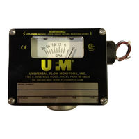
STANDARD VANE IN-LINE VARIABLE AREA FLOWMETER CONTROL BOXES WITH TRANSMITTERS
Brand:
Dwyer Instruments
| Category:
Measuring Instruments
| Size: 2 MB
Table of Contents
Table of Contents
2
2 General Vane Piston Switch Manual
5
Nameplates and Product ID
5
Installation
7
3 Vane/Piston AX/H
8
Maximum Dimensions
8
Quick Set up
9
Wiring Using Pre-Installed Wires
9
Wiring Removing Pre-Installed Wires
9
Introduction to HART Field Device Specifications
9
Scope
9
Purpose
9
Who Should Use this Document
9
Abbreviations and Definitions
10
Process Interface
10
Magnetic Sensors
10
Host Interface Analog Output 1: Process Flow
10
Dynamic Variables
11
Status Information
11
Additional Device Status (Command #48)
11
Burst Mode
12
Catch Device Variable
12
Device-Specific Commands
12
Command #128: Read Alarm Setpoints
12
Request Data Bytes
12
Response Data Bytes
12
Command #129: Write Low Alarm Setpoint
13
Request Data Bytes
13
Response Data Bytes
13
Command-Specific Response Codes
13
Command #131: Reset Totalizer
13
Command-Specific Response Codes
14
Performance
14
Sampling Rates
14
Power-Up
14
Reset
14
Self-Test
14
Command Response Times
14
Annex A: Capability Checklist
15
4 Vane/Piston AXØ
16
Maximum Dimensions
16
Nameplates and Product ID
17
5 Vane/Piston RX/H
19
Maximum Dimensions
19
Installation
23
References
23
Device Identification
23
Product Overview
25
Process Interface
25
Magnetic Sensors
25
Host Interface: Process Flow
25
Status Information
26
Extended Device Status
26
Universal Commands
27
Common-Practice Supported Commands
27
Command-Specific Response Codes
27
Command #130: Write High Alarm Setpoint
28
Request Data Bytes
28
Response Data Bytes
28
Command-Specific Response Codes
28
Tables
28
Flow Unit Codes
28
Unit Conversion
29
Perfomance
29
Busy and Delayed-Response
29
Long Messages
29
Non-Volatile Memory
29
Modes
29
Write Protection
29
Damping
29
Annex B. Default Configuration
29
6 Vane/Piston TX/H
30
Maximum Dimensions
30
Installation
33
Device Identification
33
Product Overview
34
Process Interface
34
Magnetic Sensors
34
Host Interface: Process Flow
34
Status Information
35
Extended Device Status
35
Universal Commands
36
Common-Practice Supported Commands
36
Burst Mode
36
Catch Device Variable
36
Device-Specific Commands
36
Command #129: Write Low Alarm Setpoint
37
Request Data Bytes
37
Response Data Bytes
37
Command-Specific Response Codes
37
Command #131: Reset Totalizer
37
Command-Specific Response Codes
38
Performance
38
Sampling Rates
38
Power-Up
38
Reset
38
Self-Test
38
Command Response Times
38
Annex A: Capability Checklist
39
7 Vane/Piston TX/TXL
40
Nameplates and Product ID
40
Set Low Flow Alarm
43
Advertisement
Advertisement
Related Products
Dwyer Instruments Series APM
Dwyer Instruments SAH-22-IN
Dwyer Instruments SN Series
Dwyer Instruments SM Series
Dwyer Instruments SAH SMART Air Hood Series
Dwyer Instruments Smart Air Hood SAH Series
Dwyer Instruments SAH-22
Dwyer Instruments SAH-22HC
Dwyer Instruments 1207A
Dwyer Instruments Categories
Measuring Instruments
Transmitter
Switch
Controller
Thermometer
More Dwyer Instruments Manuals
Login
Sign In
OR
Sign in with Facebook
Sign in with Google
Upload manual
Upload from disk
Upload from URL