Sign In
Upload
Manuals
Brands
Digi Manuals
Wireless Router
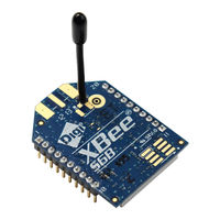
XB2B-WFUT-001
Digi XB2B-WFUT-001 Manuals
Manuals and User Guides for Digi XB2B-WFUT-001. We have
1
Digi XB2B-WFUT-001 manual available for free PDF download: User Manual
Digi XB2B-WFUT-001 User Manual (200 pages)
Wi-Fi RF Module
Brand:
Digi
| Category:
Wireless Router
| Size: 2 MB
Table of Contents
Customer Support
2
Table of Contents
4
Applicable Firmware and Hardware
12
Technical Specifications
13
General Specifications
14
RF Characteristics
14
RF Data Rates
14
Receiver Sensitivity
15
RF Transmit Power - Typical
16
Error Vector Magnitude (EVM) Maximum Output Power - Typical
17
Electrical Specifications
18
Serial Communication Specifications
19
UART Pin Assignments
20
SPI Pin Assignments
20
GPIO Specifications
20
Regulatory Conformity Summary
21
Hardware
22
Mechanical Drawings
23
Through-Hole Device
23
Surface-Mount Device
24
Pin Signals
24
Design Notes
26
Power Supply
26
Pin Connection Recommendations
27
Board Layout
27
Antenna Performance
27
Design Notes for the RF Pad Version
29
Mounting Considerations
32
Operation
33
Serial Interface
34
UART Data Flow
34
Serial Data
34
SPI Communications
35
Select the SPI Port
36
Serial Buffers
37
Serial Receive Buffer
37
Serial Transmit Buffer
37
UART Flow Control
37
CTS Flow Control
38
RTS Flow Control
38
The Commissioning Button
38
Connection Indicators
39
The Associate LED
40
TCP Connection Indicator
40
Remote Manager Connection Indicator
40
Perform a Serial Firmware Update
40
Modes
42
Serial Modes
43
Transparent Operating Mode
43
API Operating Mode
43
Command Mode
44
Modes of Operation
46
Idle Mode
46
Transmit Mode
46
Receive Mode
47
Configuration Mode
47
Sleep Mode
48
Sleep Modes
48
Soft AP Mode
48
Enable Soft AP Mode
49
Station (STA) Connection in Soft AP Provisioning Mode
49
Use the Webpage to Configure a Connected Device
49
Station (STA) Connection in Soft AP Pass through Mode
50
Sleep Modes
52
About Sleep Modes
52
Use the UART Sleep Mode
52
Use the SPI Sleep Mode
52
AP Associated Sleep Mode
53
Pin Sleep Mode
53
Cyclic Sleep Mode
53
Deep Sleep (Non-Associated Sleep) Mode
53
Pin Sleep Mode
54
Cyclic Sleep Mode
54
Use Sleep Modes to Sample Data
54
Bgn Networks
56
Infrastructure Networks
56
Infrastructure Wireless Network
56
Ad Hoc Networks
56
Set Ad Hoc Creator Parameters
56
Set Ad Hoc Joiner Parameters
57
Network Basics
57
Standards
57
Encryption
58
Authentication
58
Open Authentication
58
Shared Key
58
Channels
58
IP Services
60
Xbee Application Service
61
Local Host Access
61
Network Client Access
62
Serial Communication Service
67
Transparent Mode
67
Udp
67
Tcp
68
API Mode
68
UDP Mode
68
TCP Mode
68
I/O Support
69
Analog and Digital I/O Lines
70
Through-Hole Device
70
Surface-Mount Device
70
Configure I/O Functions
71
I/O Sampling
72
Queried Sampling
73
Periodic I/O Sampling
73
Change Detection Sampling
74
Example
74
Rssi Pwm
74
Wi-Fi Protected Setup (WPS)
76
Enable WPS Use WPS Pre-Shared Key (PSK) Mode Security
76
Generalpurposeflashmemory
79
General Purpose Flash Memory
79
Work with Flash Memory
79
Access General Purpose Flash Memory
79
General Purpose Flash Memory Commands
80
PLATFORM_INFO_REQUEST (0X00)
81
PLATFORM_INFO (0X80)
81
ERASE (0X01)
81
ERASE_RESPONSE (0X81)
82
WRITE (0X02) and ERASE_THEN_WRITE (0X03)
83
WRITE _RESPONSE (0X82) and ERASE_THEN_WRITE_RESPONSE (0X83)
83
READ (0X04)
84
READ_RESPONSE (0X84)
84
FIRMWARE_VERIFY (0X05) and FIRMWARE_VERIFY_AND_INSTALL(0X06)
85
FIRMWARE_VERIFY_RESPONSE (0X85)
86
FIRMWARE_VERIFY _AND_INSTALL_RESPONSE (0X86)
86
Update the Firmware Over-The-Air
87
Over-The-Air Firmware Updates
87
Distribute the New Application
87
Verify the New Application
88
Install the Application
88
Configure the Xbee Wi-Fi RF Module Using Digi Remote Manager
89
Use XCTU to Enable Remote Manager
90
Configure the Device
90
Output Control
91
IO Command Bits
91
Send I/O Samples to Remote Manager
92
View I/O Samples in Remote Manager
92
Update the Firmware
93
Send Data Requests
93
Enable Messages to the Host
93
About the Device Request and Frame ID
94
Populate and Send a Device Request Frame (0Xb9)
94
Transparent Mode Data
95
Send Data to Remote Manager
95
AT Command Settings to Put Serial Data in Remote Manager
95
Send Files
96
Send Binary Data Points
96
Receive Data from Remote Manager
97
API Operation
98
API Mode Overview
99
API Frame Specifications
99
API Operation (AP Parameter = 1)
99
API Operation with Escaped Characters (AP Parameter = 2)
99
Escape Characters
100
Start Delimiter Field
100
Length Field
100
Frame Data
101
Checksum Field
101
API Examples
101
API UART and SPI Exchanges
102
AT Command Frames
102
Transmit and Receive RF Data
102
Remote at Commands
102
Frame Descriptions
104
TX (Transmit) Request: 64-Bit - 0X00
104
Remote at Command Request - 0X07
106
AT Command Frame - 0X08
108
Zigbee Transmit Packet - 0X10
109
Zigbee Explicit Transmit Packet - 0X11
111
Zigbee Remote at Command - 0X17
114
Transmit (TX) Request: Ipv4 - 0X20
116
Send Data Request - 0X28
118
Device Response - 0X2A
120
Rx (Receive) Packet: 64-Bit - 0X80
121
Remote Command Response - 0X87
123
AT Command Response Frame - 0X88
125
Transmission Status Frame - 0X89
126
Modem Status Frame - 0X8A
127
Zigbee TX Status Frame - 0X8B
128
I/O Data Sample RX Indicator Frame - 0X8F
130
Zigbee Receive Packet Frame 0X90
132
Description
134
Format
134
Example
134
Zigbee Remote at Command Response Frame - 0X97
136
RX (Receive) Packet: Ipv4 - 0Xb0
138
Send Data Response Frame - 0Xb8
140
Device Request Frame - 0Xb9
141
Device Response Status Frame - 0Xba
142
Frame Error - 0Xfe
143
AT Commands
144
Addressing Commands
145
EQ (Device Cloud FQDN)
145
LA (Lookup IP Address of FQDN)
145
PG (Ping an IP Address)
145
NS (DNS Address)
145
DL (Destination Address Low)
146
MY (IP Network Address)
146
MK (IP Address Mask)
146
GW (Gateway IP Address)
146
SH (Serial Number High)
147
SL (Serial Number Low)
147
NI (Node Identifier)
147
DE (Destination Port)
147
KP (Device Description)
147
KC (Device Cloud Contact)
148
KL (Device Location)
148
C0 (Serial Communication Service Port)
148
DD (Device Type Identifier)
148
NP (Maximum RF Payload Bytes)
148
Network Commands
149
DO (Device Options)
149
ID (Ssid)
149
AH (Network Type)
150
IP (IP Protocol)
150
MA (IP Addressing Mode)
150
TM (Timeout)
151
TS (TCP Server Socket Timeout)
151
CE (Infrastructure Mode)
151
Security Commands
151
EE (Encryption Enable)
151
PK (Security Key)
152
RF Interfacing Commands
152
PL (Power Level)
152
CH (Channel)
153
Serial Interfacing Commands
153
AP (API Enable)
153
AO (API Options)
153
BD (Interface Data Rate)
154
NB (Serial Parity)
154
SB (Stop Bits)
155
RO (Packetization Timeout)
155
FT (Flow Control Threshold)
155
D7 (DIO7 Configuration)
155
D6 (DIO6 Configuration)
156
I/O Settings Commands
156
IS (Force Sample)
156
IR (I/O Sample Rate)
157
IC (Digital Change Detection)
157
IF (Sample from Sleep Rate)
157
P0 (DIO10 Configuration)
158
P1 (DIO11 Configuration)
158
P2 (DIO12 Configuration)
158
P3 (Dout)
159
P4 Din
159
P5 (DIO15 Configuration)
160
P6 (DIO16 Configuration)
160
P7 (DIO17 Configuration)
160
P8 (DIO18 Configuration)
161
P9 (DIO19 Configuration)
161
D0 (DIO0/AD0/ CB Configuration)
162
D1 (DIO1/AD1 Configuration)
162
D2 (DIO2/AD2 Configuration)
163
D3 (DIO3/AD3 Configuration)
163
D4 (DIO4/AD4 Configuration)
164
D5 (DIO5 Configuration)
164
D8 (DIO8 Configuration)
164
D9 (DIO9 Configuration)
165
LT (Associate LED Blink Time)
165
PR (Pull-Up Resistor)
166
PD (Pull Direction)
167
DS (Drive Strength)
167
AV (Analog Voltage Reference)
167
M0 (PWM0 Duty Cycle)
168
M1 (PWM1 Duty Cycle)
168
Output Control
168
IO (Set Output Pins)
168
OM (Output Mask)
168
T0 (Set Time to Hold DIO0)
169
T1 (Set Time to Hold DIO1)
169
T2 (Set Time to Hold DIO2)
169
T3 (Set Time to Hold DIO3)
169
T4 (Set Time to Hold DIO4)
169
T5 (Set Time to Hold DIO5)
170
T6 (Set Time to Hold DIO6)
170
T7 (Set Time to Hold DIO7)
170
T8 (Set Time to Hold DIO8)
170
T9 (Set Time to Hold DIO9)
170
Q0 (Set Time to Hold DIO10)
171
Q1 (Set Time to Hold DIO11)
171
Q2 (Set Time to Hold DIO12)
171
Q3 (Set Time to Hold DIO13)
171
Q4 (Set Time to Hold DIO14)
172
Q5 (Set Time to Hold DIO15)
172
Q6 (Set Time to Hold DIO16)
172
Q7 (Set Time to Hold DIO17)
172
Q8 (Set Time to Hold DIO18)
173
Q9 (Set Time to Hold DIO19)
173
Diagnostics Interfacing
173
VR (Firmware Version)
173
HV (Hardware Version)
173
HS (Hardware Series)
174
AI (Association Indication)
174
DI (Device Cloud Indicator)
175
AS (Active Scan)
175
TP (Temperature)
176
CK (Configuration Code)
176
Supply Voltage)
176
LM (Link Margin)
176
Command Mode Options
176
CT (Command Mode Timeout)
177
CN (Exit Command Mode)
177
GT (Guard Times)
177
CC (Command Mode Character)
177
Sleep Commands
178
SM (Sleep Mode)
178
SP (Sleep Period)
178
SO (Sleep Options)
178
WH (Wake Host)
179
ST (Wake Time)
179
SA (Association Timeout)
179
Execution Commands
180
AC (Apply Changes)
180
WR (Write)
180
RE (Restore Defaults)
180
FR (Software Reset)
180
NR (Network Reset)
181
CB (Commissioning Pushbutton)
181
Regulatory Information
182
United States (FCC)
183
OEM Labeling Requirements
183
FCC Notices
183
FCC-Approved Antennas (2.4 Ghz)
185
RF Exposure
190
Europe (CE)
191
Maximum Power and Frequency Specifications
191
OEM Labeling Requirements
191
Declarations of Conformity
192
Approved Antennas
192
Canada (IC)
193
Labeling Requirements
193
Transmitters with Detachable Antennas
193
Detachable Antenna
193
Australia (Rcm)/New Zealand (R-NZ)
194
Brazil (ANATEL)
194
Recommended Solder Reflow Cycle
196
Recommended Footprint
196
Mount the Devices
198
Flux and Cleaning
199
Rework
200
Advertisement
Advertisement
Related Products
Digi XBEEPRO2
Digi XBP09-XC...
Digi XBee3 XB3M1
Digi XBIB-U-DEV
Digi XB3-C-N1-UT-001
Digi XBee 3 Cat 1
Digi XB3-C-GM2-UG-101
Digi XB3-C-GM2-UT-102
Digi XB3-C-G1-UT-101
Digi XBee RR PRO
Digi Categories
Network Router
Control Unit
Modem
Gateway
Server
More Digi Manuals
Login
Sign In
OR
Sign in with Facebook
Sign in with Google
Upload manual
Upload from disk
Upload from URL