Sign In
Upload
Manuals
Brands
Delphi Manuals
Laboratory Equipment
Multec 3.5
Delphi Multec 3.5 Fuel Injector Manuals
Manuals and User Guides for Delphi Multec 3.5 Fuel Injector. We have
1
Delphi Multec 3.5 Fuel Injector manual available for free PDF download: Applications Manual
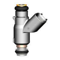
Delphi Multec 3.5 Applications Manual (178 pages)
Top Feed Fuel Injector
Brand:
Delphi
| Category:
Laboratory Equipment
| Size: 4 MB
Table of Contents
Table of Contents
5
1 0 Introduction
11
Scope of Document
11
Classification
11
Document Management
11
Document Release and Updates
11
Commercial Considerations
11
Objectives of this Manual
11
How this Manual Is Arranged
12
Conventions Used in this Manual
14
Hyperlinks
15
Applicable Documents
15
Order of Precedence
15
Government Documents
15
Other Delphi Reference Documents
15
Industry Documents
16
Useful Web Sites
16
2 0 Fundamentals
17
General
17
Engine Combustion Fundamentals
18
Figure 2-1- Engine Fuel System (Shown Is a Demand Fuel Rail for a V6 Application)
18
Air/Fuel Ratio Effects on Combustion
19
Table 2-1 - Stoichiometry of Alternate Fuel Blends
20
Figure 2-2 - Air Fuel Ratio Effect on Catalytic Converter Efficiency
22
Fuel Atomization
23
Fuel Spray Characteristics and Injection Timing
24
Benefits of Electronic Fuel Injection over Other Types of Fuel Systems
25
Impact of Transient Conditions on Combustion
25
Impact of Fuel Composition
26
Figure 2-3 - Fuel Distillation Curve Vs Temperature
29
Engine-Vehicle Environment
30
Figure 2-4 - 50% Vapor / Liquid Ratio Vs RVP, Fuel and Pressure
33
Maximum Power Fueling Requirements
35
Injector Flow Tolerances
36
Fuel Flow Considerations
36
Minimum Fuel Pump Flow Output
37
Nominal Fuel Pump Output
37
Fuel Pump Check Valve Requirements
38
Pressure Regulator Gain/Considerations (Vacuum Biased)
38
Impact of Emissions Requirements
39
The Impact of Emission Requirements on Fuel Control Systems
39
Figure 2-5 - Fuel Pressure Regulator and Gain Calculation
39
Figure 2-6 - Engine Management System Open Loop Vs Closed Loop System Architecture
40
Figure 2-7 - Catalytic Converter Efficiency Vs Air/Fuel Ratio
40
Fuel Injector Design Effects on Evaporative Emissions
41
Figure 2-8 California Tailpipe Emissions Limits
41
Impact of Canister Purge on Engine Fueling
42
Figure 2-9 - Evaporative Emissions Regulations
42
Impact of EGR and PCV on Engine Fueling
43
Injector Flow Characterization
43
3 0 Product Description
45
Scope
45
General Description
45
Figure 3-1 - Top Feed Port Fuel Injection
46
Appearance
47
Exterior Outline
47
Failure Diagnostics
47
Usage Definition
47
Physical Specifications
47
Dimensions
47
Figure 3-2 - Multec 3.5 Fuel Injector Dimensions - Seal Ring Design. (for Exact Dimensions, Refer to Delphi Injector Outline Drawing)
48
Figure 3-3 - Multec 3.5 Fuel Injector Dimensions - Cushion Seal / Face Seal Design
48
Dimensions, Refer to Delphi Injector Outline Drawing
48
Mass
49
Identification and Markings
49
Internal Components
49
Figure 3-4 - Injector Identification and Markings
49
Injector Retaining Clip
50
Figure 3-5 Multec 3.5 Internal Components
50
Seal Rings
51
Figure 3-6 -Injector Retaining Clip Designs
51
Cushion Seal Injector Design
52
Injector Design
52
Figure 3-7 - Multec 3.5 Magnetic Circuit
54
Figure 3-8 - Multec 3.5 Fuel Flow Path
54
Dual Spray Fuel Injector
55
Figure 3-9 - Dual Spray Injector
55
Injector Controls - Controller Drive Circuit
56
Minimum Operating Voltage (MOV)
56
Driver Considerations
56
Driver Circuit Clamping Voltage
57
Injector Polarity
57
Injector Flow Rate Sizing
57
Injector Targeting, Placement and Cone Angle
65
Targeting
65
Figure 3-10 - Injector Targeting
65
Cone Angle
66
Spray Atomization
67
Figure 3-11 - Dual Spray Injector Separation and Orientation Angle
69
Figure 3-12 - Sample Single and Dual Spray Injector Patternator Results
70
Pulse-Width Limits
71
Figure 3-13 Injector Opening and Closing Response
71
Minimum Pulse-Width (MPW)
72
Figure 3-14 - High Pulse-Width Flow Effects. Static Occurs at 10 Msec (Rep. Rate = 10 Msec)
73
Figure 3-15 - Low Pulse-Width Flow Effects. (Rep. Rate = 10Msec)
73
Tailbiting
74
Linear and Working Flow Range
75
3.10.1 Linear Range
75
Figure 3-16 - Injector Flow Curve Tailbiting
75
3.10.2 Working Flow Range
77
Tip Leakage
78
Figure 3-18 - Injector Working Flow Range
78
3.11.1 Total Fuel System Tip Leakage Monte Carlo Analysis
79
Contamination Resistance
80
Dynamic and Static Fuel Flow Specifications
80
Figure 3-19 Fuel Rail Total Tip Leak Monte Carlo Simulation Example (4 Cylinder)
80
3.13.1 Flow Test Fluid Specification
81
Noise
82
Electrical Specifications
82
3.15.1 Solenoid Coil Specifications
82
3.15.2 Avalanche Energy
82
Environmental Conditions
83
3.16.1 Hot Fuel Handling
83
Table 3-1 Solenoid Electrical Properties
83
Table 3-2 - Injector Environmental Operating Conditions
83
3.16.2 Environmental Exposure
84
4 0 System Interface
85
General
85
Figure 4-1 - Block Diagram
85
Interface Control Document
86
Mechanical Interfaces
87
Locating the Fuel Injector
87
Orienting the Injector
88
Figure 4-2 - Example of Recommended Mounting Feature Dimensions
88
Vibration Levels
89
Fuel Supply System Interface
91
Figure 4-3 - Example of Data Presentation for Steady State Rpm
91
Figure 4-4 - Typical Spectral Map
91
Seal Rings
92
Electrical Interface
93
Electromagnetic Compatibility
93
Wire Routing
93
Fuel Injector Polarity
94
Figure 4-5 Injector Connector Polarity
94
Fuel Injector Connector
95
Figure 4-6 - Injector Electrical Connectors
95
Figure 4-7 - Metri-Pack Harness Connector
96
Figure 4-8 - USCAR Harness Connector
97
Controller
98
Figure 4-9 - Electrical Schematic of Saturated Switch Injector Driver Circuit
99
Figure 4-10 - Oscilloscope Trace of Injector Avalanche Energy Measurement
100
5 0 Software
101
General
101
Control Algorithms
102
Injection Methods
102
Open Loop Injector and Fuel Rail Characterization
104
Figure 5-1 - Injector Firing Schemes (Red Bar = Injection Event)
104
Figure 5-2 - Slope and Intercept Graph (Flow Vs. Pulse Width)
105
Open-Loop Characterization
109
Closed-Loop Corrections
114
Fuel Injection Timing
115
Figure 5-3 - Sequential Injection Timing Considerations (4500 Rpm)
116
Diagnostics
117
Fuel Trim Diagnostics
117
Oxygen Sensor Diagnostics
118
Catalytic Converter Diagnostics
118
Injector Driver Diagnostics
118
Engine Misfire Diagnostics
118
Factors Affecting Engine Diagnostics
119
6 0 Product Handling
121
Table 6-1 - Multec 3.5 Injector Handling
122
Packing Procedures
123
Figure 6-1 Injector Seal Ring Installation Precaution
123
Receiving and Storage
124
Movement Within the Plant
124
Installation in Fuel Rail
124
Installation on the Engine
125
Component Assembly Best Practices
128
Table 6-2 - Recommended Seal Ring Lubricants
128
Maintenance, Service and Repair
129
Diagnosing Malfunction Codes
129
Replacement Techniques
129
Adjustments
131
Interchangeability
131
Support of Component after Sale
131
7 0 Recommendations and Precautions
133
Temperature
133
Durability
134
Injector Characteristics
135
Wear and Contamination
135
Internal Corrosion
135
External Exposure
135
Plugging
136
Contamination Resistance
136
Fuel System Generated Contamination
137
Maximum Fuel Pressure
137
Injector Storage
137
Preventing Engine Hydro-Lock
138
Engine Prime Pulse at Start
138
Vehicle Assembly Fuel System Prime
139
Injector Harness Connector - Corrosion
139
8 0 Testing Recommendations and Precautions
141
Dynamometer Testing
141
Cylinder-To-Cylinder Distribution
141
Durability Testing
141
Dynamic Vehicle Testing
142
Standard Vehicle Development Tests
142
Hot Fuel Handling
142
Spray Effect on Emissions
143
Cold Driveability and Startability
143
Table 8-1 - Injector Tip Soak Temperature Vs Required Fuel Pressure
143
Crank Vs. Leak
144
Altitude Driveability and Emissions
144
Low Pulse-Width Fueling Accuracy
144
Driveability Index Fuel Sensitivity
144
Spark Plug Fouling Tests
145
Voltage Sensitivity
145
8.4.10 Manifold Pressure Sensitivity
145
8.4.11 Standard Durability Tests
145
8.4.12 Icing Tests
145
8.4.13 Production Limit Verification Tests
145
9 0 Validation Requirements
147
General
147
Validation Tests
147
Preliminary Physical Analysis
148
Environmental Exposure
148
External Corrosion
148
Temperature
149
Life Cycling
149
Mechanical Integrity
150
Table 9-1 - Potential Injector Test Fuels
150
Overpressurization
151
Over-Voltage
151
Injector Noise
152
Note on Additional Exposures
152
Verification
152
Table 9-2 - Injector Verification Matrix Template
153
10 0 Appendix
155
Introduction
155
Multec 3.5 Fuel Injector System Customer Component Checklist
156
Component Application Checklist
162
Component Assembly Best Practices
166
Glossary of Terms and Abbreviations
171
11 0 Index
173
Advertisement
Advertisement
Related Products
Delphi Categories
Receiver
Cables and connectors
Car Receiver
Radio
GPS
More Delphi Manuals
Login
Sign In
OR
Sign in with Facebook
Sign in with Google
Upload manual
Upload from disk
Upload from URL