Table of Contents

Subscribe to Our Youtube Channel
Summary of Contents for Delphi Multec 3.5
- Page 1 Multec 3.5 Top Feed Fuel Injector Application Manual Fuel Systems Applications Engineering Delphi Energy & Chassis Systems 5500 W. Henrietta Rd. P.O. Box 20366 Rochester, New York 14602 USA Delphi Energy and Chassis Systems 2005...
- Page 3 Multec 3.5 Fuel Injector Application Manual Revision Summary Multec 3.5 Top Feed Fuel Injector Application Manual Release/Revision Summary Sheet CHANGE NO. DATE REASON FOR CHANGE PAGE(S) Issued April 2004 July 2005 Replaced “J-spray…” with “J-2715 (Draft)” in section 1.9.4.2 Nov. 05 Added shutdown throttle closure note to section 8.4.4...
- Page 4 Multec 3.5 Fuel Injector Application Manual Revision Summary Nov 05 Renumbered pages in section 4 starting at 1 Nov 05 Changed dwell time from 1 hr to 0.5 hr and duration from 240 hours to 120 hours in section 9.3.2.1...
-
Page 5: Table Of Contents
Multec 3.5 Fuel Injector Application Manual Table of Contents Table of Contents 1. 0 INTRODUCTION ................1-1 ........................1-1 COPE OF OCUMENT ..........................1-1 LASSIFICATION ....................... 1-1 OCUMENT ANAGEMENT 1.3.1 Document Release and Updates ..................1-1 ....................... 1-1 OMMERCIAL ONSIDERATIONS ......................1-1... - Page 6 Table of Contents Multec 3.5 Fuel Injector Application Manual 3.2.3 Usage Definition ........................3-3 3.2.4 Failure Diagnostics....................... 3-3 ......................3-3 HYSICAL PECIFICATIONS 3.3.1 Dimensions........................... 3-3 3.3.2 Mass ............................. 3-5 3.3.3 Identification and Markings ....................3-5 3.3.4 Internal Components ......................3-5 3.3.5 Injector Retaining Clip ......................
- Page 7 Multec 3.5 Fuel Injector Application Manual Table of Contents ............................. 4-8 EAL RINGS ........................4-9 LECTRICAL NTERFACE 4.4.1 Electromagnetic Compatibility....................4-9 4.4.2 Wire Routing......................... 4-9 4.4.3 Fuel Injector Polarity......................4-10 4.4.4 Fuel Injector Connector ......................4-11 4.4.5 Controller ..........................4-14 5. 0 SOFTWARE ..................5-1 ............................
- Page 8 Table of Contents Multec 3.5 Fuel Injector Application Manual 7.3.7 Injector Storage ........................7-5 ....................7-6 REVENTING NGINE YDRO LOCK 7.4.1 Engine Prime Pulse at Start ....................7-6 7.4.2 Vehicle Assembly Fuel System Prime ................. 7-7 – C ................7-7...
- Page 9 Figure 2-9 - Evaporative Emissions Regulations.................. 2-26 Figure 3-1 - Top Feed Port Fuel Injection....................3-2 Figure 3-2 - Multec 3.5 Fuel Injector Dimensions – Seal ring design. (For exact dimensions, refer to Delphi Injector Outline Drawing)....................... 3-4 Figure 3-3 – Multec 3.5 Fuel Injector Dimensions – Cushion seal / Face seal design (For exact dimensions, refer to Delphi Injector Outline Drawing.
- Page 10 Table of Contents Multec 3.5 Fuel Injector Application Manual Figure 6-2 Injector Installation Surface ....................6-5 Figure 7-1 - Thermocoupled injector......................7-2 Delphi Energy and Chassis Systems Revision: 11/05-01...
-
Page 11: 1.0 Introduction
Delphi leadership and its commitment to continuous improvement and world-class quality. This Multec 3.5 Fuel Injector Application Manual has been developed to support the efforts to integrate the Multec 3.5 Fuel Injector into a specific fuel system or engine management system. Delphi Energy Chassis Systems... -
Page 12: How This Manual Is Arranged
Multec 3.5 Fuel Injector To accomplish these objectives, this manual provides the following: • A description of the components and features of the Multec 3.5 Fuel Injector • A description of the process used to determine the requirements needed to achieve the following objectives: −... - Page 13 Calibration and diagnostics are also discussed. Understanding this section is critical to achieving optimum performance from the Multec 3.5 Fuel Injector. Section 6.0 — Product Handling Section 6.0 presents Delphi recommendations for the handling, storage, installation, and servicing of the fuel injector.
-
Page 14: Conventions Used In This Manual
• Caution —Indicates information about a condition or an activity that must be performed to prevent damage to the Multec 3.5 Fuel Injector, fuel system, electronic control system, engine or the vehicle. • Warning —Indicates a condition that might pose a risk to personal safety. -
Page 15: Hyperlinks
Government Documents To be supplied by customer for specific country. 1.9.3 Other Delphi Reference Documents 1.9.3.1 Multec 3.5 Fuel Injector specific Part Number and associated outline drawing 1.9.3.2 Multec 3.5 Fuel Injector Component Technical Specification (or equivalent document) if available 1.9.3.3 Delphi Fuel Rail Applications Manual 1.9.3.4... -
Page 16: Industry Documents
Introduction Multec 3.5 Fuel Injector Application Manual 1.9.4 Industry Documents 1.9.4.1 SAE Standard Procedure J1832 1.9.4.2 SAE J-2715 (Draft) Gasoline Fuel Injector Spray Measurements and Characterizations 1.9.4.3 ASTM D86, “Standard Test Method for Distillation of Petroleum Products at Atmospheric Pressure”... -
Page 17: 2.0 Fundamentals
Fundamentals 2.0 Fundamentals General The Multec 3.5 Fuel Injector is a component of the Air/Fuel Subsystem. The function of the fuel injector is to provide the required fuel quantity and spray geometry to the each engine cylinder to meet vehicle performance and emissions requirements over a wide range of operating conditions. -
Page 18: Engine Combustion Fundamentals
If a more detailed explanation is required on any of these topics, please contact Delphi Energy and Chassis Systems. The following text is suggested for those who would like a more... -
Page 19: Air/Fuel Ratio Effects On Combustion
Fundamentals 2.2.1 Air/Fuel Ratio Effects on Combustion The goal of the Multec 3.5 Fuel Injector is to supply the correct fuel mass to achieve the correct air/fuel ratio (A/F). Complete combustion will depend, in general, on the following: • The air and fuel must be in the proper portions (referred to as the stoichiometric mixture or ratio);... -
Page 20: Table 2-1 - Stoichiometry Of Alternate Fuel Blends
Fundamentals Multec 3.5 Fuel Injector Application Manual Since the A/F will vary depending on the makeup of hydrocarbons in the gasoline, a more appropriate method for referencing A/F is to use a normalized value. In this way, we can refer to stoichiometric A/F as equal to 1, regardless of the makeup of the gasoline. - Page 21 Multec 3.5 Fuel Injector Application Manual Fundamentals design, fuel quality (contaminants and other non-combustibles) and the limited time available to complete the process (especially at high engine rpm.) all contribute to less than ideal combustion. A catalytic converter is usually used in the exhaust system to transform...
-
Page 22: Figure 2-2 - Air Fuel Ratio Effect On Catalytic Converter Efficiency
Fundamentals Multec 3.5 Fuel Injector Application Manual Conversion Efficiency for a Typical Three-Way Catalyst Rich Region: where little O Lean Region: where excess O available, so reduction can easily available to oxidize HC & CO. be done to NO . (Reduction... -
Page 23: Fuel Atomization
Fundamentals combustible dilutant can reduce NOx. One of the most common of these is exhaust gas, recirculated into the mixture via an EGR system. (Ref. Delphi EGR Applications Manual for more information on this process). 2.2.1.5 Non-Combustible Mixtures Air/fuel ratios outside the combustible mixture limits (too rich or too lean) cause engine misfire, reduced power, a significant increase in emissions (primarily HC from unburned fuel) and poor overall engine performance. -
Page 24: Fuel Spray Characteristics And Injection Timing
See Section 5 for Typically, open intake valve fuel injection timing is not recommended for calibrating optimum conventional fuel injection systems with Multec 3.5 injectors because the injection timing fuel bypasses the heating effects of the intake valve. If injection takes... -
Page 25: Benefits Of Electronic Fuel Injection Over Other Types Of Fuel Systems
+/- 1.0 cylinder to cylinder In addition, evaporative emissions standards require closed fuel systems using seal rings and minimal tip leakage. The Multec 3.5 injector is a dry coil design. There are no internal seal rings, eliminating possible sources of evaporative emissions. -
Page 26: Impact Of Fuel Composition
Fundamentals Multec 3.5 Fuel Injector Application Manual Caution Extreme transient conditions can require low pulse-widths. Commanded pulse-widths must not fall below the application’s minimum specifications. Inconsistencies in injector flow, pulse-to-pulse and part-to-part result when operated below minimum recommended ranges. 2.2.6 Impact of Fuel Composition 2.2.6.1... - Page 27 15% MTBE or 10% denatured ethanol). Higher percentages of alcohols will shorten the operating life of the injector. Please consult a Delphi representative to obtain a current list of all fuels the Multec 3.5 Fuel Injector has been validated in.
- Page 28 Fundamentals Multec 3.5 Fuel Injector Application Manual 2.2.6.3.2 Aromatics (approx. 35 %mass) As aromatic concentration increases: • Increases octane rating • Increases energy content (increases fuel economy) • Makes fuel more difficult to burn • Reduces fuel volatility • Increases self ignition temperature •...
-
Page 29: Figure 2-3 - Fuel Distillation Curve Vs Temperature
Multec 3.5 Fuel Injector Application Manual Fundamentals Figure 2-3 - Fuel Distillation Curve vs Temperature 2.2.6.4 Driveability Index A more complete understanding of the impact of fuel volatility on fuel system performance can be obtained by measuring the fuel’s distillation curve and computing the driveability index (DI). -
Page 30: Engine-Vehicle Environment
Fundamentals Multec 3.5 Fuel Injector Application Manual 2.2.7 Engine-Vehicle Environment 2.2.7.1 Impact of High Engine Temperatures on Combustion As the engine and engine compartment temperatures increase, several factors must be considered to obtain optimum combustion. Hot air entering the induction system is lower in density and results in a reduced mass air flow rate. - Page 31 Multec 3.5 Fuel Injector Application Manual Fundamentals volatility. The volatility of gasoline is measured by the RVP (Reid Vapor Note Pressure). Typically, RVP is stated as the pressure required to suppress ° ° the formation of vapor at 100 F (38 C.) Fuel in the vapor state...
- Page 32 Fundamentals Multec 3.5 Fuel Injector Application Manual • High volatility fuel is being used. This includes high RVP gasoline, especially moderate to high RVP ethanol/ methanol blends of gasoline. One method of reducing susceptibility to hot re-start problems is to raise the fuel system operating pressure above this vaporization pressure.
-
Page 33: Figure 2-4 - 50% Vapor / Liquid Ratio Vs Rvp, Fuel And Pressure
Multec 3.5 Fuel Injector Application Manual Fundamentals 50% Vapor / 50% Liquid Temperature of Gasoline and E-10 350 & 400 kPa System Pressures Gas-350 kPa E10-350 kPa Gas-400 kPa E10-400 kPa 7 RVP 8 RVP 9 RVP 10 RVP 11 RVP... - Page 34 Fundamentals Multec 3.5 Fuel Injector Application Manual 2.2.7.3 Cold Engine/ Cold Ambient Effects on Combustion During cold engine starts, additional fuel is required to make a combustible mixture due to the fact that the fuel will not vaporize as readily on the cold engine surfaces. Fuel atomization and spray distribution are extremely critical during this phase since there is little heat for fuel vaporization.
-
Page 35: Maximum Power Fueling Requirements
Low system voltage not only affects the output of the fuel pump, but can also affect the ability of the injector to open (a minimum operating voltage (MOV) is specified for each Multec 3.5 injector model). Customer startability requirements under these conditions must be fully understood prior to the correct selection of the fuel rail assembly and fuel pump. -
Page 36: Injector Flow Tolerances
Fundamentals Multec 3.5 Fuel Injector Application Manual Likewise, it is sometimes necessary to protect the catalyst from high temperature degradation by enrichment of the intake fuel charge. This condition is typically referred to as catalyst protection or catalyst over- temperature protection (COT). Such a condition might be seen under high load conditions, such a towing a trailer or climbing a steep grade. -
Page 37: Minimum Fuel Pump Flow Output
Multec 3.5 Fuel Injector Application Manual Fundamentals 2.3.1 Minimum Fuel Pump Flow Output The minimum fuel pump output must provide enough fuel to maintain regulated fuel pressure during all engine running modes. Regulated fuel pressure is defined as the pressure reached when the fuel pressure regulator has enough fuel passing through it to adequately control the fuel pressure in the rail. -
Page 38: Fuel Pump Check Valve Requirements
• Check valve relief pressure is greater than the maximum required fuel pump pressure to achieve regulated system pressure in worst case conditions. Note: The maximum relief pressure recommended for the Multec 3.5 injector is 1000 kPa. 2.3.4 Pressure Regulator Gain/Considerations (Vacuum Biased) -
Page 39: Impact Of Emissions Requirements
Multec 3.5 Fuel Injector Application Manual Fundamentals Figure 2-5 - Fuel Pressure Regulator and Gain Calculation Impact of Emissions Requirements 2.4.1 The Impact of Emission Requirements on Fuel Control Systems For vehicle applications with more stringent legal exhaust emissions limits, a closed-loop fuel control system with a catalytic converter may be required. -
Page 40: Figure 2-6 - Engine Management System Open Loop Vs Closed Loop System Architecture
Fundamentals Multec 3.5 Fuel Injector Application Manual Figure 2-6 - Engine Management System Open Loop vs Closed Loop System Architecture Figure 2-7 - Catalytic Converter Efficiency vs Air/Fuel Ratio The fuel rail assembly should provide controlled pressure and a steady flow of fuel to the injectors. -
Page 41: Fuel Injector Design Effects On Evaporative Emissions
Increasingly stringent evaporative emissions requirements place additional demands on the sealing capabilities of the fuel system (see Figure 2-9). The Multec 3.5 Injector contributes to reduced evaporative emissions by: 1. Reduced injector tip leakage 2. Elimination of internal seal rings which can be a source of permeation. -
Page 42: Impact Of Canister Purge On Engine Fueling
Fundamentals Multec 3.5 Fuel Injector Application Manual Evaporative Emissions Limits Evaporative emissions source: Fuel System and Vehicle Vehicle Only Fuel System Only PZEV Figure 2-9 - Evaporative Emissions Regulations 2.4.3 Impact of Canister Purge on Engine Fueling To reduce the amount of vehicle evaporative emissions, a contained fuel storage and supply system is used to minimize the escape of fuel vapors from the fuel tank to the atmosphere. -
Page 43: Impact Of Egr And Pcv On Engine Fueling
Delphi suggests collecting fuel calibration data with the entire fuel system – fuel rail conduits, fuel injectors and fuel pressure regulator. This will allow the fuel calibration to compensate for fuel distribution variation and fuel pressure regulator gain. - Page 44 Typically a function of regulator gain. Can be minimized by using rail flow data for recirculating systems. For Demand fuel systems Delphi normally provides flow data at a constant rail fuel pressure. Any regulator gain correction must be done as part of the fuel pump correction.
-
Page 45: 3.0 Product Description
The Multec 3.5 Fuel Injector is a top-feed design for port fuel injection systems (Figure 3-1). Depending on the application, one or more Multec 3.5 Fuel Injectors can be used for each cylinder. -
Page 46: Figure 3-1 - Top Feed Port Fuel Injection
Engine Intake Valve Fuel Spray Figure 3-1 - Top Feed Port Fuel Injection The Multec 3.5 injector is currently designed with either • Upper and lower seal rings (Figure 3-2) • Upper seal ring and lower face seal. (Figure 3-3) The upper seal ring provides a seal between the rail conduit and the injector to prevent fuel leakage. -
Page 47: Appearance
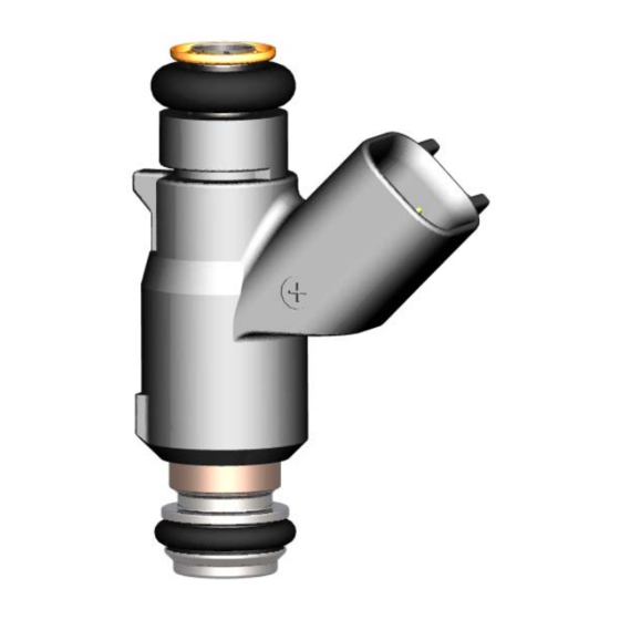
Multec 3.5 Fuel Injector Application Manual Product Description 3.2.1 Appearance The standard Multec 3.5 Fuel Injector has a black plastic upper body, with a stainless steel (silver color) lower body. 3.2.2 Exterior Outline The injector exterior outline meets underhood packaging constraints per vehicle specifications. -
Page 48: Figure 3-2 - Multec 3.5 Fuel Injector Dimensions - Seal Ring Design. (For Exact Dimensions, Refer To Delphi Injector Outline Drawing)
Figure 3-2 - Multec 3.5 Fuel Injector Dimensions – Seal ring design. (For exact dimensions, refer to Delphi Injector Outline Drawing). Figure 3-3 – Multec 3.5 Fuel Injector Dimensions – Cushion seal / Face seal design (For exact dimensions, refer to Delphi Injector Outline Drawing. -
Page 49: Mass
3.3.2 Mass The mass of the Multec 3.5 Fuel Injector varies slightly with fuel injector length and type. An approximate value for mass is 35.2 grams for a "long" version, and 31.5 grams for a "mini" version (includes clip and seal rings). -
Page 50: Injector Retaining Clip
Product Description Multec 3.5 Fuel Injector Application Manual Rail Seal Ring Filter Calibration Tube Pole Piece Coil Valve Valve Spring Valve Seat Director Manifold Director Seal Ring Retainer Figure 3-5 Multec 3.5 Internal Components 3.3.5 Injector Retaining Clip The injector clip (refer to Figure 3-6) is typically supplied as part of the injector assembly and provides the following functions: •... -
Page 51: Seal Rings
They must also be resistant to varying amounts of fuel additives to fuel (i.e., ethanol, etc.). The following are currently available seal rings designs. Please contact a Delphi representative if the specific sealing requirements are not met by these designs: Injector to fuel rail seal ring •... -
Page 52: Cushion Seal Injector Design
E-85 compatible injector. Dual- cone spray and skewed spray options are available. The magnetic circuit and flow path in the Multec 3.5 injector is optimized to allow one injector configuration to satisfy static flow rates from 1 to 4 g/s at 300 to 400 kPa. - Page 53 Multec 3.5 Fuel Injector Application Manual Product Description The fuel injector meters fuel to the engine based on the duration of the voltage signal received from the engine controller drive circuit. During each cylinder cycle the injector receives a voltage signal energizing the coil and creating a magnetic field.
-
Page 54: Figure 3-7 - Multec 3.5 Magnetic Circuit
Multec 3.5 Fuel Injector Application Manual Tube Pole Piece Coil Outer Body Valve Magnetic Armature Flux Path Body Figure 3-7 - Multec 3.5 Magnetic Circuit Fuel Flow Path Figure 3-8 - Multec 3.5 Fuel Flow Path 3-10 Delphi Energy and Chassis Systems Revision: 11/05-1... -
Page 55: Dual Spray Fuel Injector
Various cone and separation angles are available to meet application specifics. See Section 3.3.5 All Multec 3.5 injectors incorporate a locating post in the encapsulation for orientation. The injector retaining clip is designed to engage the encapsulation post and control rotational orientation of the injector in the fuel rail socket to maintain the proper spray targeting to intake valve relationship. -
Page 56: Injector Controls - Controller Drive Circuit
Injector Controls – Controller Drive Circuit There are two principal types of injector drivers: saturated switch and peak-and-hold. All Multec 3.5 injectors are designed to use the saturated switch driver. A saturated switch drive circuit is used with injectors having relatively high resistance, generally 11 to 16 ohms. -
Page 57: Driver Circuit Clamping Voltage
• Fuel system pressure information will be used to determine director hole size. • The Multec 3.5 injector magnetic circuit is designed for system operating pressures of 300 kPa to 500 kPa (43.5 psi to 72.5 psi.) • The fuel supply system should be designed to include pressure relief to prevent the injector from being exposed to pressures greater than 1000 kPa (145 psi.) Pressure in excess of 1000 kPa... - Page 58 Product Description Multec 3.5 Fuel Injector Application Manual ∆ • ∆ Note: The following calculations assume an ideal constant fuel supply for pressure vs. injector flow. Any fuel pressure control deviations from the set point must be taken into consideration in the following calculations.
- Page 59 Multec 3.5 Fuel Injector Application Manual Product Description 3. Engine’s Brake Specific Fuel Consumption (BSFC) ratio • BSFC is the ratio of measured engine fuel flow to engine horsepower output (Lb /HP*Hour) It is determined on a dynamometer and is a function of RPM. If data is available, the engineer should use the BSFC value at peak horsepower RPM.
- Page 60 Product Description Multec 3.5 Fuel Injector Application Manual 6. Vehicle Calibration Dependent Issues • When sizing injector flow rate for any engine/vehicle application, the engineer should also consult the fuel calibration engineer for calibration specific fuel concerns. An example list is: −...
- Page 61 Multec 3.5 Fuel Injector Application Manual Product Description See Section 3.9.2 3. Adjust the value to eliminate injector operation in the tail-biting region (if required). (Assume a 5% adjustment.) (20.0 gm/sec) * 1.05 = 21.0 gm/sec See Section 7.2 4. Adjust the value to account for possible injector durability flow shift (lean).
- Page 62 Product Description Multec 3.5 Fuel Injector Application Manual Additional assumptions for the following calculation − One injector per cylinder − Sequential injector firing Engine repetition rate = [1/ RPM] * [(60 sec/min)* (2 rev/inject)* (1000msec/sec) Example @ 600 RPM: Engine rep rate...
- Page 63 Multec 3.5 Fuel Injector Application Manual Product Description Example: Min flow = 0.46 gm/sec @ (400 kPa fuel pressure + 50 kPa Vac=450 kPa injector pressure drop.) Max flow = 3.68 g/s @ (400 kPa fuel pressure – 0 kPa Vac = 400 kPa injector pressure drop.)
- Page 64 Product Description Multec 3.5 Fuel Injector Application Manual Injector Flow Worksheet Program Name: The following values must be determined before calculating maximum fuel flow per injector. • Engine horsepower rating (HP) _________ − @ Engine RPM _________ • Brake Specific Fuel Consumption (BSFC)
-
Page 65: Injector Targeting, Placement And Cone Angle
Cold start strategies for reduced emissions may require alternate spray targeting schemes. Delphi has extensive spray visualization and measurement capabilities to help determine the optimum spray targeting for an application. -
Page 66: Cone Angle
Cone Angle The injector spray cone angle is a measure of the included angle containing a specified percentage of the fuel. At Delphi spray cone angles are measured using a spray patternator consisting of a grid of hex shaped cells that collect the fuel spray and measure the volume distribution. -
Page 67: Spray Atomization
• Systems testing with Delphi support may be necessary to determine the optimum spray configuration to meet specific engine performance and emissions goals. This may include high speed video recording of fuel injection events in the running application engine, cold start emissions, steady state emissions, and transient response. - Page 68 This parameter is useful in understanding the overall droplet size distribution spread. Spray atomization measurements at Delphi are typically performed with a Laser Diffraction instrument. The beam is located 100 mm from the injector tip which is actuated at pulse width to deliver 15 mg/pulse of N- Heptane.
-
Page 69: Figure 3-11 - Dual Spray Injector Separation And Orientation Angle
Multec 3.5 Fuel Injector Application Manual Product Description 100 mm Figure 3-11 - Dual Spray Injector Separation and Orientation Angle Delphi Energy and Chassis Systems Revision: 11/05-1 3-25... -
Page 70: Figure 3-12 - Sample Single And Dual Spray Injector Patternator Results
Product Description Multec 3.5 Fuel Injector Application Manual Spray Plot w/ Transducer Grid Spray Parameters Injector Height : 143 mm Test Description Connector Angle (θ) : 0° Test EWO # : Fuel Pressure : 400 kPa Part # : Pulse Width : 5 ms... -
Page 71: Pulse-Width Limits
Multec 3.5 Fuel Injector Application Manual Product Description Pulse-Width Limits Fuel delivery becomes unpredictable at high duty cycles (>95%) and very low pulse-widths due to unstable opening and closing times. Opening response (O.R.) is the time it takes the magnetic circuit to build... -
Page 72: Minimum Pulse-Width (Mpw)
Product Description Multec 3.5 Fuel Injector Application Manual − System voltage − System pressure Error! Bookmark not defined. − Injector body temperature − Wiring resistance and (affects coil resistance) connector resistance − Fuel lubricity − Injector part-to-part tolerances − Injector flow calibration −... -
Page 73: Figure 3-14 - High Pulse-Width Flow Effects. Static Occurs At 10 Msec (Rep. Rate = 10 Msec)
Multec 3.5 Fuel Injector Application Manual Product Description Figure 3-14 - High Pulse-Width Flow Effects. Static Occurs at 10 msec (rep. rate = 10 msec) Figure 3-15 - Low Pulse-Width Flow Effects. (Rep. rate = 10msec) Delphi Energy and Chassis Systems... -
Page 74: Tailbiting
Product Description Multec 3.5 Fuel Injector Application Manual 3.9.2 Tailbiting Refer to Figure 3-16. The trace for driver logic represents the commanded signal to the injector. The trace for injector valve stroke is an example of the actual response of the injector to this input. This trace represents the result of commanding the injector to open before the injector has fully closed from the previous input signal. -
Page 75: Linear And Working Flow Range
Multec 3.5 Fuel Injector Application Manual Product Description Injector Stroke ( µ m) 1.04 Injector Current (Amps) 12.5 Injector Voltage (Volts) Driver Logic 0.5 ms Time Figure 3-16 - Injector Flow Curve Tailbiting Linear and Working Flow Range 3.10 3.10.1 Linear Range Linear Range is a measure of the portion of an injector flow curve that is linear. - Page 76 Product Description Multec 3.5 Fuel Injector Application Manual Single Or Mean Flow Curve Single Or Mean Regression Line Linear Range 10.0 1 0 .0 Pulse Width (ms) 5 .0 0 .0 -5 .0 -1 0 .0 Figure 3-17 - Linear Range...
-
Page 77: 3.10.2 Working Flow Range
Multec 3.5 Fuel Injector Application Manual Product Description 3.10.2 Working Flow Range Working Flow Range is a measure of injector-to-injector flow variation based on a production population of at least 24 injectors. It impacts cylinder-to-cylinder air/fuel ratio. Working Flow Range = Maximum flow divided by the minimum... -
Page 78: Tip Leakage
Product Description Multec 3.5 Fuel Injector Application Manual 3 . 0 2 . 5 M e a n F lo w C u r v e 2 . 0 1 . 5 W o r k in g F lo w R a n g e 1 . -
Page 79: 3.11.1 Total Fuel System Tip Leakage Monte Carlo Analysis
Multec 3.5 Fuel Injector Application Manual Product Description When using gaseous leak check techniques (bubble, pressure decay, or mass flow), it is imperative to perform an injector internal drying procedure by cycling the injector with pressurized clean dry air prior to leak test. -
Page 80: Contamination Resistance
Product Description Multec 3.5 Fuel Injector Application Manual of rails to exceed the limit. See Figure 3-19 for a sample rail tip leak Monte Carlo distribution. Injector Tip Leak Monte Carlo for 4 Cylinder Rail 5000 Rail Build Simulations 98.7% 99.1% 99.3% 99.5% 99.9% 97.0%... -
Page 81: 3.13.1 Flow Test Fluid Specification
The injector is set for both static and dynamic flow during the manufacturing process. Multec 3.5 injectors are capable of static flow rates from 1.3 to 4.0 g/s at 400kPa (58 psi.) Static flow rates above 4 g/s are feasible, but may require relaxed flow tolerances due to increased pressure sensitivity. -
Page 82: Noise
Electrical Specifications 3.15 3.15.1 Solenoid Coil Specifications Solenoid electrical specifications for the Multec 3.5 Fuel Injector are presented in Table 3-1. 3.15.2 Avalanche Energy Avalanche Energy supplements inductance as a solenoid specification parameter relevant to injector driver requirements. Avalanche Energy is the inductive energy stored in the magnetic field of the solenoid that is released back into the driver circuit when voltage is switched off. -
Page 83: Environmental Conditions
Table 3-1 Solenoid Electrical Properties Environmental Conditions 3.16 The Multec 3.5 Fuel Injector is designed to operate in a certain range of conditions but can withstand extreme operating conditions for short periods of time. Table 3-2 lists typical examples of normal and extreme operating conditions. -
Page 84: 3.16.2 Environmental Exposure
3.16.2 Environmental Exposure The Multec 3.5 Fuel Injector meets performance and physical requirements for environmental conditions it may be exposed to, as defined by Delphi Validation Plans (see section 9.) The fuel injector is compatible with specifications for: Ozone Humidity... -
Page 85: 4.0 System Interface
Multec 3.5 Fuel Injector Application Manual System Interface 4.0 System Interface General The Multec 3.5 Fuel Injector interfaces with the other Engine & Vehicle Subsystems as described in this section and shown in Figure 4-1. Vibration Contamination Fuel Quality Underhood... -
Page 86: Interface Control Document
System Interface Multec 3.5 Fuel Injector Application Manual 4.1.1 Interface Control Document INTERFACE CONTROL DOCUMENT TO/FROM INTERFACE INTERFACE INTERFACE NAME DESCRIPTION SECTION Wiring Required for attachment, Vehicle Harness available from Delphi-P • Refer to Section 4.4.2 Control Provide interface for injector... -
Page 87: Mechanical Interfaces
Mechanical Interfaces 4.2.1 Locating the Fuel Injector Properly locating the Multec 3.5 Fuel Injector on the engine contributes to satisfactory long-term operation. The recommendations provided below should serve as a guide for hardware planning. • To provide adequate air circulation to cool the injector and prevent heat Clearance transfer from the surrounding components, e.g., fuel rails and the intake... -
Page 88: Orienting The Injector
System Interface Multec 3.5 Fuel Injector Application Manual • To prevent fuel collection at the injector tip and surrounding port Tip Location surfaces do not recess the injector tip from the airflow. 4.2.1.1 Limits on Injector Position The fuel injector should be located to meet the following requirements... -
Page 89: Vibration Levels
Before a validation statement can be completed, the vibration levels need to be analyzed for each application. If resistance to dynamometer engine vibration levels (usually higher than vehicle levels) is required, this should be communicated to the Delphi Design Engineer. 4.2.3.2... - Page 90 Multec 3.5 Fuel Injector Application Manual 5. Data can be compared if they are presented in the format typically used at Delphi. RPM spectral maps and power spectra are needed. Use the following parameters for analyzing the data: • Hanning window •...
-
Page 91: Fuel Supply System Interface
Multec 3.5 Fuel Injector Application Manual System Interface Figure 4-3 - Example of data presentation for steady state rpm. Figure 4-4 - Typical Spectral Map 4.2.4 Fuel Supply System Interface Fuel is normally supplied to the injector by a fuel rail, which should be... -
Page 92: Seal Rings
Caution Do not use lubricant that will cause harm to oxygen sensors, (such as those based upon or containing silicone). Reference Delphi Oxygen Sensor Application Manual. Warning It is preferred to not reuse the seal rings when re-installing an injector. If re-use is necessary, carefully inspect each seal ring for any signs of damage, as even minor defects can lead to fuel / vacuum leakage. -
Page 93: Electrical Interface
4.4.1 Electromagnetic Compatibility Generation: The Multec 3.5 Fuel Injector should not produce any objectionable RFI in AM, FM, and CB bands. EMI/RFI can occur in two ways: radiated through surrounding air and conducted through connecting wires. Suppression of the EMI occurs in the injector driver circuit Zener diode. -
Page 94: Fuel Injector Polarity
Multec 3.5 Fuel Injector Application Manual 4.4.3 Fuel Injector Polarity The Multec 3.5 Fuel Injector utilizes a 2 terminal electrical connector. The terminals correspond to power and ground and are not polarity dependent for injector performance, yet a polarity has been established to reduce the severity of a coil short to the injector body from a full-on condition to a blown fuse. -
Page 95: Fuel Injector Connector
System Interface 4.4.4 Fuel Injector Connector • The Multec 3.5 injector is available with two electrical connector styles: • "Metri-Pack" splash-proof type design • USCAR standard connector design (immersion-proof) The USCAR connector design is more robust to environmental exposure and is therefore recommended over the metri-pack design. -
Page 96: Figure 4-7 - Metri-Pack Harness Connector
System Interface Multec 3.5 Fuel Injector Application Manual Metri-Pack design: Component Part Number Description Electrical 12110179 or Splash proof connector Connector & 12129140 or Seal equivalent Terminal 12077939 or equivalent Retaining Latch Figure 4-7 - Metri-Pack Harness Connector 4-12 Delphi Energy and Chassis Systems... -
Page 97: Figure 4-8 - Uscar Harness Connector
Multec 3.5 Fuel Injector Application Manual System Interface USCAR 1.5 mm terminal connector design (SAE/USCAR-12 design guideline). Component Part Number Description Electrical USCAR mating connector 15355226 Connector & Seal Cable Seal 12176807 Or equivalent 12176636 Terminal 15326238 Terminal Position Assurance feature... -
Page 98: Controller
Note It is recommended to use a non-wicking grade cable on the wires leading to the injectors. This is a commercially available product from Delphi - Packard Electric Systems. This is to address the failure mode of fuel wicking from the injector to the engine control module. -
Page 99: Figure 4-9 - Electrical Schematic Of Saturated Switch Injector Driver Circuit
Typically, maximum single event avalanche energy and repetitive avalanche energy values are required for the controller. The avalanche energy for the Multec 3.5 injector is the same for all injector applications due to the common coil design. -
Page 100: Figure 4-10 - Oscilloscope Trace Of Injector Avalanche Energy Measurement
System Interface Multec 3.5 Fuel Injector Application Manual Injector Current Injector Logic Voltage Current * Voltage Figure 4-10 - Oscilloscope trace of injector avalanche energy measurement 4-16 Delphi Energy and Chassis Systems Revision: 11/05-1... -
Page 101: 5.0 Software
Multec 3.5 Fuel Injector Application Manual Software 5.0 Software General Refer to Section 2.2.1.1 An ideal air fuel (A/F) ratio provides minimum emissions and maximum fuel economy and driveability. For any given engine and vehicle operating condition, there is an optimum A/F ratio. It is the function of the engine controller’s software to calculate the optimum A/F ratio for the... -
Page 102: Control Algorithms
Software Multec 3.5 Fuel Injector Application Manual • The mass airflow system directly measures the airflow into the cylinders using a mass airflow sensor normally placed at the at the throttle body inlet. Control Algorithms The following closed-loop and open-loop software sections briefly describe engine and engine management system components that typically influence air/fuel control and thereby impact control of the fuel injector. - Page 103 Multec 3.5 Fuel Injector Application Manual Software 5.2.1.3 Alternating Simultaneous Double Fire (ASDF) Injectors are pulsed in groups twice every combustion cycle, once every crankshaft revolution (the amount of injectors in each group usually equals 1/2 of the number of cylinders). One half the required fuel for each combustion event is injected with each injector pulse.
-
Page 104: Open Loop Injector And Fuel Rail Characterization
Software Multec 3.5 Fuel Injector Application Manual Figure 5-1 - Injector Firing Schemes (red bar = injection event) 5.2.2 Open Loop Injector and Fuel Rail Characterization For ease of calculation and calibration, the engine controller’s software assumes the injector is a linear device. As a linear device, the injector can be characterized by the slope in the traditional Y = M*X + B equation of a line. -
Page 105: Figure 5-2 - Slope And Intercept Graph (Flow Vs. Pulse Width)
Multec 3.5 Fuel Injector Application Manual Software M = Slope (grams/sec/msec) X = Pulse-width (msec) B = Y intercept (grams/sec) Note It is best if the slope and intercept are determined by flowing a fuel rail assembly. This will then include pressure regulator effects (for a recirculating fuel system) and rail pressure dynamic effects. - Page 106 Software Multec 3.5 Fuel Injector Application Manual 3. The BPW is then compared to the minimum PW. If the BPW is less than the minimum allowable PW, the BPW is set to the minimum PW, or the injector firing scheme is altered, to increase the PW above the minimum.
- Page 107 Multec 3.5 Fuel Injector Application Manual Software 5.2.2.2 Injector Offset Since the injector flow curve does not go through the origin, an “offset” is needed (See Figure 5-2). “Offset” refers to the amount of time that is added to (or subtracted from) the engine controller-calculated pulse-width.
- Page 108 Software Multec 3.5 Fuel Injector Application Manual fuel flow at small pulse-widths. The correction effectively extends the dynamic range of the fuel system by decreasing the minimum usable pulse-width. (See section 3.10.2) Most software can correct pulse-widths of approximately 3.9 ms and lower.
-
Page 109: Open-Loop Characterization
Multec 3.5 Fuel Injector Application Manual Software flow deviates significantly from the predicted linear flow through either non-linearity or excessive variation. • For control software that has low pulse width correction (see section 5.2.2.3), compensation can be made for the non-linearity, so the injector population variation is the determining criteria for minimum pulse-width. - Page 110 Software Multec 3.5 Fuel Injector Application Manual open-loop characterization determines the accuracy of the actual delivered air/fuel ratio. 5.2.3.1 Volumetric Efficiency (VE) Volumetric Efficiency corrects the base pulse-width for pumping inefficiencies and various errors inherent in the system. The speed density equation assumes perfect induction, combustion, and exhaust.
- Page 111 Multec 3.5 Fuel Injector Application Manual Software 5.2.3.4 Altitude/Barometer Correction Altitude/barometer correction is used to compensate for changes in air density at different altitudes. 5.2.3.5 Engine Coolant Temperature (ECT) The engine coolant temperature signal is used to compensate fueling during warm-up. Due to the lower fuel vapor formation rates at cooler temperatures, the ECT signal schedules richer air/fuel ratios to achieve a combustible mixture in the cylinder.
- Page 112 Software Multec 3.5 Fuel Injector Application Manual 5.2.3.9 Catalytic Converter Protection Mode Under certain conditions, catalytic converter temperatures can exceed manufacturer recommendations. An option to reduce temperature in the converter is to add additional fuel (catalytic converter protection mode). Resulting A/F ratios may be richer than power enrichment A/F ratios.
- Page 113 Multec 3.5 Fuel Injector Application Manual Software can result in high emissions and potentially high converter temperatures. Added benefits of DFCO can be reduced fuel consumption and lower emissions. Transitions from fuel-off to fuel-on must occur smoothly. Wall Wetting, Fuel Puddling Even with careful injector targeting, a certain amount of fuel overlaps the intake valve and hits the walls, reducing the amount of fuel for that pulse.
-
Page 114: Closed-Loop Corrections
Software Multec 3.5 Fuel Injector Application Manual Top Speed Limiters Top speed limiters shut off the fuel when the vehicle goes above a predetermined speed (MPH or KPH). Fail Soft (Limp Home ) If a sensor fails, the vehicle will still operate by using the remaining sensors to predict the failed sensor’s reading. -
Page 115: Fuel Injection Timing
Multec 3.5 Fuel Injector Application Manual Software when the air/fuel ratio is close to stoichiometric. Integral correction is a slower (several milliseconds and smaller) step change. The amount of correction increases in relation to the length of time that the error exists. -
Page 116: Figure 5-3 - Sequential Injection Timing Considerations (4500 Rpm)
Software Multec 3.5 Fuel Injector Application Manual Figure 5-3 - Sequential injection timing considerations (4500 rpm) The following factors affect fuel residence time in the manifold and need to be considered when calibrating injection timing: • As RPM increases, the time available between valve open events decreases and the fuel pulse-width and fuel transport time in crank angle degrees increases. -
Page 117: Diagnostics
Multec 3.5 Fuel Injector Application Manual Software fuel metered at the intended port. Occurrence of this is highly dependent on fundamental engine and intake port design (i.e. relative locations and sizes of port areas). In this case, delaying the arrival of fuel at the intake valve (closer to valve opening) may reduce port fueling errors. -
Page 118: Oxygen Sensor Diagnostics
Software Multec 3.5 Fuel Injector Application Manual 5.3.2 Oxygen Sensor Diagnostics The signal of an oxygen sensor normally swings up and down between about 0.8 and 0.2 volts one or more times every second. A condition of mal-distribution can cause the pre-converter oxygen sensor to oscillate at the frequency of the engine (RPM). -
Page 119: Factors Affecting Engine Diagnostics
Multec 3.5 Fuel Injector Application Manual Software 5.3.6 Factors Affecting Engine Diagnostics • Air calculations • Temperature • Manifold pressure • System voltage errors (voltage drop due to vehicle wiring) • Gain consideration (electrical and mechanical) • Adequate fuel system capacity •... -
Page 121: 6.0 Product Handling
Multec 3.5 Fuel Injector Application Manual Product Handling 6.0 Product Handling The purpose of this section is to become familiar with the Delphi recommended handling procedures for the Multec 3.5 Fuel Injector. These recommendations cover storage practices and all handling that may occur from the time the injector enters until it leaves the customer’s plant. -
Page 122: Table 6-1 - Multec 3.5 Injector Handling
DO NOT: Stack units on top of each other. Damage may be done to critical components. DO NOT: Tap on fuel injectors to correct any malfunction. Can damage injector. Table 6-1 – Multec 3.5 Injector Handling Delphi Energy and Chassis Systems Revision: 11/05-1... -
Page 123: Packing Procedures
Figure 6-1 Injector Seal Ring Installation Precaution Packing Procedures The Multec 3.5 Fuel Injector is an electrical component and must be handled with reasonable care to prevent damage. Proper handling starts at the Delphi manufacturing operation where the packaging methods used help reduce the risk of damage due to impact, moisture, or contamination. -
Page 124: Receiving And Storage
Caution The Multec 3.5 Fuel Injector should never be exposed to liquid contamination. Should water enter the injector’s solenoid assembly through the connector, fuel inlet or injector tip, damage could occur. -
Page 125: Installation On The Engine
Lubrication 10 light mineral oil or equivalent is recommended. (See Table 6-2) Additional lubricants can be evaluated by Delphi for injector sticking and corrosion and added to the approved listing. • The preferred technique is to apply the lubricant to the sockets the injectors are being installed into, rather than directly to the seal ring itself. - Page 126 • Seal rings are not interchangeable between Multec 3, and Multec 2 Warning: and Multec 1 injectors. Consult service parts listing for proper replacement. • The Multec 3.5 Fuel Injector is not a handle. Do not use the injector to Do not use the injector as a lift attached assemblies.
- Page 127 Multec 3.5 Fuel Injector Application Manual Product Handling • Carefully installing the harness connector will prevent terminal Harness connector damage. Listen for a positive audible click from the connector retention device — this ensures that it is fully engaged. If the...
-
Page 128: Component Assembly Best Practices
Product Handling Multec 3.5 Fuel Injector Application Manual • Exercise care that the injector connector tab is not damaged during Connector tabs installation. If the tab becomes damaged, the electrical connector may disconnect in the future causing a customer complaint for engine misfire. -
Page 129: Maintenance, Service And Repair
• Before a leak check, pulse the injector to make sure the valve is properly seated. 6.7.2 Replacement Techniques The following procedure outlines standard Multec 3.5 Fuel Injector removal and replacement. 1. Shut off ignition. Warning The injector and all associated hardware may be extremely hot. - Page 130 Product Handling Multec 3.5 Fuel Injector Application Manual 7. Remove the injector from the fuel rail. Delphi recommends the use of a specific Multec 3.5 removal tool (which is currently in development) to aid in the removal of the injector. (Consult your Delphi representative for current information).
-
Page 131: Adjustments
Note: All Multec 3.5 injectors use a 12 Ohm coil and the 0.5A setting An Ohmmeter test is intended to detect the deterioration of injector coils... - Page 132 Product Handling Multec 3.5 Fuel Injector Application Manual • Rough idle • Engine misfire or surge • Stall after start or hard starting • Failure of emissions testing • Poor fuel economy • Exhaust odor 6-12 Delphi Energy and Chassis Systems...
-
Page 133: 7.0 Recommendations And Precautions
Temperatures that are either too cold or too hot for prolonged periods of time must be avoided. System designs and software routines that maintain temperatures within the Multec 3.5 Fuel Injector’s designed range will prolong injector life and ensure optimum performance. (See Table 3-2) 1. -
Page 134: Durability
Recommendations and Precautions Multec 3.5 Fuel Injector Application Manual Figure 7-1 - Thermocoupled injector Durability Injector flow performance will vary over its usable life due to mechanical wear and deposit build up. This variation must fall within defined acceptable limits over the application’s target life. Injector performance may vary as follows: •... -
Page 135: Injector Characteristics
• Injector tip leakage may increase due to excessive wear of the ball seat sealing surfaces. 7.2.1 Injector Characteristics Multec 3.5 injector field durability flow shift limits are available for each injector model on the Injector Outline Drawing available from Delphi. These limits are based on the application’s fuel usage and operating environments. -
Page 136: Plugging
• Increased levels of detergent additives reduce the rate of injector plugging. • The Multec 3.5 injector features a recessed director design to reduce the exposure of the director surface to deposit forming engine combustion by-products, which contribute to plugging. -
Page 137: Fuel System Generated Contamination
(fuel lines, fuel rail, fuel pump, fuel tank). Substances of the types mentioned above should be evaluated by Delphi for potential injector damage or deposit formation. Where the effect of a substance is not known a production process sample may be required for evaluation of the substance’s effect on the fuel injector. -
Page 138: Preventing Engine Hydro-Lock
Gum and varnish deposits in the injector may degrade the injector flow performance. Injectors received from the Delphi production facility should be stored in a clean and dry environment before use (see section 6.2). -
Page 139: Vehicle Assembly Fuel System Prime
Multec 3.5 Fuel Injector Application Manual Recommendations and Precautions times be less than the maximum on-time calculation above to prevent hydro-lock. 7.4.2 Vehicle Assembly Fuel System Prime In some instances, at the vehicle assembly plant an injector prime pulse sequence is initiated to expedite purging a new fuel system of air prior to the initial start of the vehicle. -
Page 141: 8.0 Testing Recommendations And Precautions
Instead, some general examples specific to injectors are provided. Dynamometer Testing It is critically important that the Multec 3.5 Fuel Injector be tested under conditions that approximate normal operating conditions to ensure that fueling is accurate. A dynamometer is an ideal facility to set steady state engine conditions for evaluation. -
Page 142: Dynamic Vehicle Testing
As a guideline for 12 psi (83 kPa) RVP non-oxygenated fuel, the recommended maximum Multec 3.5 soak temperatures for acceptable hot fuel handling are as follows. The injector tip temperature is measured as... -
Page 143: Spray Effect On Emissions
Multec 3.5 Fuel Injector Application Manual Testing Recommendations and Precautions Maximum Injector Soak Temperature Recommended Fuel System Set Pressure 300 kPa T less than or equal to 95°C 350 kPa T less than or equal to 105°C 400 kPa T less than or equal to 115° C 450 kPa T less than or equal to 120°C... -
Page 144: Crank Vs. Leak
Testing Recommendations and Precautions Multec 3.5 Fuel Injector Application Manual kPa) range. Temperatures, pressures and engine control parameters should be recorded during testing to assure consistency and for a record of results. 8.4.4 Crank vs. Leak The purpose of crank versus leak is to determine the effect of injector leak rate on vehicle start times, and to determine what is an acceptable or optimum value. -
Page 145: Spark Plug Fouling Tests
Multec 3.5 Fuel Injector Application Manual Testing Recommendations and Precautions 2.2.6.4) Driveability index is a measure of the distillation curve, and is somewhat independent of the RVP of the fuel. High DI fuel typically results in sags and stalls during warm up as a result of leaner operation due to less evaporation of the fuel. - Page 146 This may include the production and durability flow shift limits for the hardware. The hardware evaluated should include the pump, regulator, and injectors. Additional information can be obtained from your Delphi representative. Delphi Energy and Chassis Systems Revision: 11/05-1...
-
Page 147: 9.0 Validation Requirements
Multec 3.5 Fuel Injector Application Manual Validation Requirements 9.0 Validation Requirements General This section outlines the validation requirements for the Multec 3.5 Fuel Injector. Validation is the process whereby the components and/or system are evaluated through methods of testing, analysis, inspection, and/or... -
Page 148: Preliminary Physical Analysis
9.3.1.1 Corrosion - Cosmetic Multec 3.5 injectors will exhibit no red rust when subjected to 32 hours of 5% neutral salt mist per ASTM B117. Injectors will not experience any loss of function, or reduction in service life as a result of this exposure. -
Page 149: Temperature
-40 to 150°C (-40 to 300°F) • Storage Temperature Range: -60°C to 60°C (-76 to 140°F ) The Multec 3.5 injector has been designed for operation within these temperature limits. Injector design modifications may be required for operation outside of these temperature limits. -
Page 150: Mechanical Integrity
All testing, unless otherwise noted, should be performed using Delphi test procedures. Multec 3.5 will be validated for durability flow performance on a number of fuels that are arrived at through Customer request or market analysis. While... -
Page 151: Overpressurization
Outline Drawing and without sustaining any permanent physical damage. 9.3.6 Over-voltage Multec 3.5 injectors will withstand high voltage exposure without loss of the ability to comply with the durability flow tolerance requirements on the Injector Outline Drawing. The test consists of exposure to voltage of 26V... -
Page 152: Injector Noise
Verification A validation matrix (see Table 9-2) has been compiled which contains the Multec 3.5 Fuel Injector Requirements that should be addressed in the Component Technical Specification. The matrix shows these requirements with a corresponding method of evaluation and the respective responsibility level for performing the validation process. -
Page 153: Table 9-2 - Injector Verification Matrix Template
Multec 3.5 Fuel Injector Application Manual Validation Requirements VERIFICATION (VALIDATION MATRIX ) ITEM METHOD LEVEL OF EVALUATION ANALYSIS TEST INSPECTION DEMONSTRATION COMPONENT SUBSYSTEM VEHICLE 3.0 REQUIREMENTS 3.1 DEFINITION 3.1.1 Appearance (new and after durability) 3.1.2 Contents (features functions) 3.1.3 Environment (usage environment) 3.1.4 External Interfaces... -
Page 155: 10.0 Appendix
10.1 This section contains three checklists intended to verify that all aspects have been considered for the proper application of the Multec 3.5 injector. The first checklist (section 10.2) covers the system related topics that need to be considered when specifying a fuel injector for a particular engine application. -
Page 156: Multec 3.5 Fuel Injector System Customer Component Checklist
Appendix Multec 3.5 Fuel Injector Application Manual Multec 3.5 Fuel Injector System Customer Component Checklist 10.2 Customer Component Checklist MPFI Injector Fuel System Subsystem Drivers for Component Application Requirements Value Selection Manual Doc. Section Reference Emissions Requirements Engine out HC, CO, NOx goals (g/mile for 2.2.1... - Page 157 Multec 3.5 Fuel Injector Application Manual Appendix For 2 intake valves per cylinder 3.3.5 applications and dual spray injectors: Injector and or retention clip to have rotational orientation feature to fuel rail − Describe recommended feature % Fuel on intake valve (by design layout) −...
- Page 158 Appendix Multec 3.5 Fuel Injector Application Manual Software and Control Interface Open-loop or closed-loop control system 2.4.1 (oxygen sensor feedback) 5.2,5.2.3 5.2.4 Speed density or mass air flow system Firing scheme at idle/off idle: Seq., SDF, Figure 5-1 ASDF, SSF Closed-loop correction authority limit 5.2.4...
- Page 159 Multec 3.5 Fuel Injector Application Manual Appendix Electrical Interface Sat. switch amps peak-and-hold amps peak current at volts 4.4.5 Min. voltage at injector required for 2.2.7.5 opening during cold ambient engine crank 3.6.1 (system pressure determined from fuel 2.3.1 pump output curves) (volts) Injector operating voltage range, engine 3.15...
- Page 160 Appendix Multec 3.5 Fuel Injector Application Manual Engine Start/Restart Requirements Min. rail inlet pressure vs. vehicle soak 2.2.7.2 time (kPa at specified time) Time to reach fuel pressure or max. cranking pressure at rail inlet. Specify temp. and conditions (secs at 2.2.7.2...
- Page 161 Multec 3.5 Fuel Injector Application Manual Appendix Others Injector mechanical and sealing interfaces 3.3.5,3.3.6,4.2 to fuel rail and head/manifold meets Delphi recommendations − Include analysis of injector clip interface Other significant component drivers 3.14 (external noise, external corrosion) specify 3.15 driver and requirement 4.4.5.1, 9.3.1...
-
Page 162: Component Application Checklist
Appendix Multec 3.5 Fuel Injector Application Manual Component Application Checklist 10.3 CHARACTERISTIC APPLICATION CAPABILITY/ RESULT MANUAL RECOMMENDATION SECTION(S) VERIFICATION Environment: Temperature 3.3.6 ‘O’-ring compatible 3.16 Acceptable to application Table 3-2 5.3.6 8.4.3 9.3.2 Corrosion 3.16.2 Acceptable to application 9.3.1 4.2.1... - Page 163 Multec 3.5 Fuel Injector Application Manual Appendix CHARACTERISTIC APPLICATION CAPABILITY/ RESULT MANUAL RECOMMENDATION SECTION(S) VERIFICATION 4.4.1 Acceptable to application Voltage 3.15 Defined limits acceptable to application 5.3.6 8.4.9 9.3.6 Dust 3.16.2 Acceptable to application Humidity 3.16.2 Acceptable to application Fuel Pressure 3.16.2...
- Page 164 Appendix Multec 3.5 Fuel Injector Application Manual CHARACTERISTIC APPLICATION CAPABILITY/ RESULT MANUAL RECOMMENDATION SECTION(S) VERIFICATION 5.2.3.14 Utilize fuel pump correction 5.3.6 Minimum Pulse Width 3.9.1 Meet application 5.2.1.4.1 recommendation 5.2.2.5 Interface: Stack-up 3.2.2 Ensure no solid contact of 3.3.1 injector with any other surface 4.2.1...
- Page 165 Multec 3.5 Fuel Injector Application Manual Appendix CHARACTERISTIC APPLICATION CAPABILITY/ RESULT MANUAL RECOMMENDATION SECTION(S) VERIFICATION Saturated switch driver utilized 3.6.3 4.4.5 Clamping voltage Avalanche Energy 3.15.2 Acceptable to application 4.4.5.1 Performance: Appearance 3.2.1 Black and Stainless Steel acceptable to application Fuel Pressure 2.2.7.2...
-
Page 166: Component Assembly Best Practices
Appendix Multec 3.5 Fuel Injector Application Manual CHARACTERISTIC APPLICATION CAPABILITY/ RESULT MANUAL RECOMMENDATION SECTION(S) VERIFICATION 8.4.2 Spray variation acceptable for 8.4.8 application Velocity Velocity and distance correct 5.2.5 for injection timing 8.4.8 Leakage 2.4.2 Durability acceptable to 3.11 application (crank vs leak) 8.4.4... - Page 167 (Please e-mail and/or fax assembly instruction documents to Bruce Gardephe @ (585 359-6361) Comments Please complete & forward information to Bruce Gardephe @ Delphi E&C. TCR, via e-mail Bruce.Gardephe@delphi.com and/or fax (585) 359-6464 Note: Any questions, concerns and/or comments please call (585) 359-6361. Thanks! again for your participation.
- Page 168 Appendix Multec 3.5 Fuel Injector Application Manual VAP: COMPONENT ASSEMBLY PRACTICES(CAP) MANUAL Reviewer: FUEL SYSTEM DATA SHEET DATE: VEHICLE ASSEMBLY PLANT(VAP) PROCESS REVIEW STORAGE - Build Date Code Part Number: Part Number: Part Number: Part Number: Date Date Date Code...
- Page 169 (Please e-mail and/or fax assembly instruction documents to Bruce Gardephe @ (585 359-6361) Comments Please complete & forward information to Bruce Gardephe @ Delphi E&C. TCR, via e-mail Bruce.Gardephe@delphi.com and/or fax (585) 359-6361 Note: Any questions, concerns and/or comments please call (585) 359-6361. Thanks! again for your participation.
- Page 170 Appendix Multec 3.5 Fuel Injector Application Manual 10-16 Delphi Energy and Chassis Systems Revision: 11/05-1...
-
Page 171: Glossary Of Terms And Abbreviations
Multec 3.5 Fuel Injector Application Manual Appendix Glossary of Terms and Abbreviations 10.5 American Automobile (Emissions) AAMA Manufacturers Association Grams Air Conditioner Horsepower Acceleration Enrichment Idle Air Control Air/Fuel Ratio IAFM Integrated Air Fuel Module ASDF Alternating Simultaneous Intake Air Temperature... - Page 172 Appendix Multec 3.5 Fuel Injector Application Manual Static Minimum Operating Delphi document containing SMOV Test Voltage Specificatio application specific injector performance specifications Start of Production n Sheet Terminal Position Assurance Set Point Flow Rate Throttle Position Sensor Simultaneous Single Fire...
-
Page 173: 11.0 Index
Multec 3.5 Fuel Injector Application Manual Index 11.0 Index CARB ............2-12, 3-17 CARB Web Site ...........1-6 2D symbology ............3-5 Catalytic Converter.....2-5, 2-6, 2-23, 2-24 Catalytic Converter Diagnostics ......5-18 Catalytic Converter Protection Mode2-20, 3-16, 5-12 Chassis Fuel Supply Subsystem ......1-2 Acceleration Enrichment ........5-12... - Page 174 Index Multec 3.5 Fuel Injector Application Manual DFMEA ..............9-1 Diagnostic Trouble Code........6-9 Face seal ..........3-2, 3-8, 6-11 Diagnostics ..........3-3, 5-17 Fail Soft (Limp Home) ........5-14 Direct injection .............2-8 Federal Emissions Test Procedure......2-8 Director..............3-1 Filter Distribution Chassis............1-2, 7-4 Air/EGR/PCV..........2-27...
- Page 175 Multec 3.5 Fuel Injector Application Manual Index Hot Fuel Handling ......2-14, 3-22, 8-2 How this Manual is Arranged.......1-2 Lambda ..............2-4 Humidity.............3-40 Leak Hydrocarbons .............2-10 Testing ..............6-6 Hydro-lock............7-6 Vacuum............5-17 Lean Mixtures............2-6 Limit testing............5-15 IAT ........ See Intake Air Temperature Linear and Working Flow Range .......3-31 Identification and Markings .........3-5...
- Page 176 Index Multec 3.5 Fuel Injector Application Manual OBD-II Diagnostic Procedures......1-6 Replacement Techniques........6-9 Objectives of this Manual........1-1 Resistance ..........3-12, 3-39 Offset ............5-5, 5-6 Returnless fuel system .2-1, 2-16, 2-17, 2-21, 2-27, 2- Olefins ..............2-12 28, 5-6, 5-10 Open Loop............5-4 Rev Limiters ............5-13...
- Page 177 Multec 3.5 Fuel Injector Application Manual Index Testing ..............1-2 Valve Stroke ............3-37 Durability............9-1 Vaporization ............2-8 Icing..............8-5 Verification(Validation Matrix) ......9-7 Recommendations and precautions ....8-1 Vibration....... 3-2, 3-40, 4-3, 8-1, 9-5 Spark Plug Fouling ...........8-5 Durability Requirements........4-5 Standard Durability ..........8-5 Measurement Techniques .........4-5 Standard Vehicle Development ......8-2...
- Page 178 Index Multec 3.5 Fuel Injector Application Manual This Page Intentionally Left Blank 11-8 Delphi Energy and Chassis Systems Revision: 11/05-1...
Need help?
Do you have a question about the Multec 3.5 and is the answer not in the manual?
Questions and answers