Sign In
Upload
Manuals
Brands
Datum Systems Manuals
Modem
PSM-500LT
Datum Systems PSM-500LT Manuals
Manuals and User Guides for Datum Systems PSM-500LT. We have
1
Datum Systems PSM-500LT manual available for free PDF download: Installation And Operation Manual
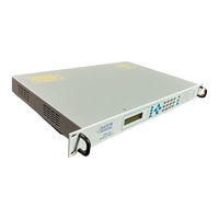
Datum Systems PSM-500LT Installation And Operation Manual (124 pages)
M500 VSAT/SCPC Satellite Modem
Brand:
Datum Systems
| Category:
Modem
| Size: 0.99 MB
Table of Contents
Table of Contents
3
Safety Notice
9
EMC Notice
9
About this Manual
10
Revision History
10
Pen and Ink Changes Made to this Manual
10
Chapter 1 - PSM-500 Modem Description
11
Introduction
11
How to Use this Manual
11
Quick Start for Experienced Modem Users
12
What's New - this Modem and this Manual
12
Modem Capabilities
12
Modem if Variations
12
Modem Feature Set Variations
13
Applications
14
SCPC Point to Multi-Point Links in a Broadcast Application
14
SCPC Point-To-Point Links
14
DAMA (Demand Assigned Multiple Access)
15
TDMA (Time Division Multiple Access) Remote Site Application
15
Modem Functional Assemblies
16
Figure 1-2 Modem Block Diagram
17
Modulator
18
Demodulator
19
Modem Bit Rate Timing
20
Figure 1-3 Clock Source Options
21
Acquisition Processor
22
Control Processor
22
Standard Data Interface
22
Data Interface 1:1 Redundancy Function
23
Data Interface BERT Function
23
Data Interface Loop-Back Function
23
Standard Framing and IBS Multiplexer
24
AUPC Control Channel (AUPC)
25
Auxiliary Bit Control Channels (RFC)
25
Modem Control Channel (MCC)
25
Remote Modem Control Channel (RMC)
25
Standard and Optional Modem FEC Cards
25
Reed-Solomon Codec Capability
28
Special Codec CT Modes
28
Viterbi, Trellis Code Modulation Codec
28
LDPC FEC Capability
30
Turbo Product Codes FEC Capability
30
Modem Circuit Implementation
31
Optional Interface Capability
31
Chapter 2 - Installation
33
Installation Requirements
33
Unpacking
33
Removal and Assembly
33
Mounting Considerations
33
Modem Connections
34
Figure 2-1 Modem Rear Panel
37
Data Interface Pin Connections
38
Table 2–1 Data Interface Connector J3 Pin Assignment by Signal
38
Connecting the Data Interface to Other Equipment
39
Remote Control Connection
39
Alarm Connection
40
Table 2–3. Alarm Connector J5 Pin Assignment
40
Auxiliary (AUX) Connection
41
L-Band BUC Power Connection
41
Table 2–4. BUC Power Connector J11 Pin Assignment
41
Redundancy Connection
41
Figure 2-2 - Modem Connections for 1:1 Redundancy
42
Set-Up Procedure for 1:1 Redundancy
43
Modem Checkout
44
Initial Power-Up
44
Modem Control from the Front Panel
44
Parameter Setup
45
Modem Terminal Mode Control
45
Self-Test Mode
46
IF Loop-Back Test Mode
46
Built-In BERT
46
Modem Configuration
47
Configuring the Modem for Operation
47
Setting Essential Parameters
47
Demodulator
47
Modulator
47
Modulator and Demodulator
47
Alternate Scrambler Mode Operation
48
Fixed Scrambler Mode Operation
48
IBS Multiplexer and Reed-Solomon Selection
48
IESS-308 Scrambler Mode Operation
48
IESS-309 Scrambler Mode Operation
48
Using the L-Band PSM-500L Transmit RF Frequency Feature
48
Using the Proper Scrambler
48
Using the L-Band & L Receive RF Frequency Feature
49
Carrier Acquisition Parameters
49
Carrier Re-Acquisition
50
Initial Acquisition
50
Sample Configuration Setting
51
Setting Additional Parameters
52
Alarm Configuration
52
Automatic Correction
52
Data Interface Compatibility
52
Figure 2-3 - Alarm Processing
53
Using the Internal or an External Reference
54
Reference Calibration
54
Setting the Modem Station ID Name
55
Setting the Modem Address for Command Mode Operation
56
Interface Type Configuration
56
Adding or Changing the Optional Interface Type
56
Option FEC Card Installation
57
Turbo Product Codes Option Installation
58
Figure 2-5 FEC Option Card Installation
59
Chapter 3 - Operation
61
Operating Procedures
61
Front Panel Control
61
Front Panel Layout and Features
61
Front Panel LCD Display
61
Front Panel Keypad
62
Demodulator LED Indicators
64
Front Panel LED Indicators
64
Modem LED Indicators
64
Modulator LED Indicators
64
Guide to Front Panel Monitor and Control
65
Navigating Modem Parameters
65
Changing Modem Parameters
66
Monitoring Modem Parameters
66
Automatic Modem Parameter Sequences
67
Finding Modem Parameter Limits
67
Front Panel Monitor and Control Parameters
67
Table 3-5. Modem (Unit) Parameter Detail
72
Table 3-6. Modulator Parameter Detail
76
Table 3-7. Demodulator Parameter Detail
80
Table 3-8. Interface Parameter Detail
85
Terminal Mode Control
87
Modem Setup for Terminal Mode
87
Figure 3-2A. Terminal Mode – Example of Unit Status Screen
88
Figure 3-2B. Terminal Mode – Example of Unit Status Screen Selection
88
Figure 3-3. Terminal Mode – Example of Unit Test Screen
89
Programming Modem Operational Values from the Terminal Screens
89
Remote Command Interface Control
90
System Unit Programming/Communications
90
Modem Checkout
90
Power-Up
91
L-Band Feature Operation
91
L-Band BUC Control
92
L-Band LNB Control
92
Data Interface Clock Options
92
VSAT Mode
92
SCPC Mode
93
Transmit Interface Clock Auto Mode
93
Automatic Uplink Power Control (AUPC) Operation
93
Demodulator Receive Data FIFO Operation
95
Built-In 1:1 Redundancy Mode Operation
96
Setting up 1:1 Redundancy Mode
97
Operating 1:1 Redundancy Mode
98
Forcing a Transfer Switch in 1:1 Redundancy Mode
98
Removal and Replacement of Units in Redundancy Mode
99
Bit Error Rate Test (BERT) Set Operation
99
Analog Monitor Output Operation
99
Storing and Recalling Configuration
100
Automatic Configuration Recovery - ACR
100
Special Control Mechanisms
101
Power-Up Behavior
101
Monitors and Outputs
101
Burst Mode Operation
101
Chapter 4 - Maintenance
103
Periodic Maintenance
103
Internal Reference Calibration
103
Common Test Procedures
103
Loop-Back Testing
103
Using the Built-In BERT
105
Troubleshooting
106
Onboard Diagnostic Indicators
108
Onboard Processor Power-On Sequence and Diagnostics
109
Built-In Lamp Test
109
Updating Modem Software
109
Update Software Installation
111
Performing the Software/Firmware Update
112
Upgrading the Modem Feature Set
116
Frequently Asked Questions - FAQ
117
Link Set up and Installation
117
Compatibility with Other Modems
117
Operating and Performance Questions
118
Why Does It Do that
120
Front Panel Control
120
Remote Control
121
Data Interface
122
Manual
123
Advertisement
Advertisement
Related Products
Datum Systems PSM-500
Datum Systems PSM-500L
Datum Systems PSM-2100L
Datum Systems PSM-4900L
Datum Systems M7 Series
Datum Systems M7D Series
Datum Systems M7DL Series
Datum Systems M7L Series
Datum Systems M7LT Series
Datum Systems M7XC
Datum Systems Categories
Modem
Monitor
Measuring Instruments
More Datum Systems Manuals
Login
Sign In
OR
Sign in with Facebook
Sign in with Google
Upload manual
Upload from disk
Upload from URL