Sign In
Upload
Manuals
Brands
Daikin Manuals
Air Conditioner
VRV III REYQ8PY1B
Daikin VRV III REYQ8PY1B Manuals
Manuals and User Guides for Daikin VRV III REYQ8PY1B. We have
3
Daikin VRV III REYQ8PY1B manuals available for free PDF download: Service Manual, Installation Manual, Operation Manual
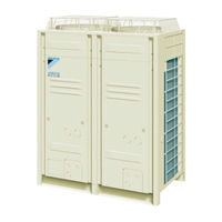
Daikin VRV III REYQ8PY1B Service Manual (472 pages)
R-410A Heat Recovery 50Hz
Brand:
Daikin
| Category:
Heating System
| Size: 18.4 MB
Table of Contents
R-410A Heat Recovery 50Hz
2
Table of Contents
2
Introduction
7
Safety Cautions
7
Preface
11
Part 1 General Information
12
Mode
12
J8" Outdoor Unit
13
Mode
13
Model Names of Indoor/Outdoor Units
13
2 External Appearance
14
Indoor Units
14
Outdoor Units
15
3 Combination of Outdoor Units
16
4 Model Selection
17
Part 2 Specifications
20
Outdoor Units
21
Indoor Units
32
BS Units
65
Part 3 Refrigerant Circuit
66
1 Refrigerant Circuit
67
Reyq8P, 10P, 12P
67
Reyq14P, 16P
69
REMQ8P (Multi 8HP)
71
REMQ10P, 12P (Multi 10, 12HP)
73
REMQ14P, 16P (Multi 14, 16HP)
75
BS Unit Functional Parts
77
Indoor Units
78
2 Functional Parts Layout
79
Reyq8P, 10P, 12P
79
Reyq14P, 16P
80
Remq8P
81
Remq10P, 12P
82
Remq14P, 16P
83
3 Refrigerant Flow for each Operation Mode
84
Part 4 Function
112
1 Function General
113
Symbol
113
Operation Mode
115
2 Basic Control
116
Normal Operation
116
Compressor PI Control
117
Electronic Expansion Valve PI Control
125
Step Control of Outdoor Unit Fans
125
Outdoor Unit Fan Control in Cooling Operation
126
Heat Exchanger Control
127
3 Special Control
128
Startup Control
128
Large Capacity Start up Control (Heating)
130
Oil Return Operation
131
Defrost Operation
135
Pump-Down Residual Operation
137
Standby
139
Stopping Operation
140
4 Protection Control
141
High Pressure Protection Control
141
Low Pressure Protection Control
143
Discharge Pipe Protection Control
145
Inverter Protection Control
146
STD Compressor Overload Protection
148
5 Other Control
149
Backup Operation
149
Demand Operation
149
Heating Operation Prohibition
149
6 Outline of Control (Indoor Unit)
150
Operation Flow Chart
150
Thermostat Control
152
Drain Pump Control
156
Control of Electronic Expansion Valve
158
Freeze Prevention
159
Heater Control (Optional PC Board KRP1B
160
List of Swing Flap Operations
161
Hot Start Control (in Heating Operation Only)
162
Louver Control for Preventing Ceiling Dirt
163
Part 5 Test Operation
164
1 Test Operation
165
Installation Process
165
Procedure and Outline
166
Operation When Power Is Turned on
198
2 Outdoor Unit PC Board Layout
199
3 Field Setting
200
Field Setting from Remote Controller
200
Field Setting from Outdoor Unit
213
Night-Time
234
Emergency Operation
237
Part 6 Troubleshooting
242
1 Symptom-Based Troubleshooting
245
2 Troubleshooting by Remote Controller
248
The INSPECTION / TEST Button
248
Self-Diagnosis by Wired Remote Controller
249
Self-Diagnosis by Wireless Remote Controller
250
Inspection Mode
253
Remote Controller Service Mode
254
Test Run Mode
256
Remote Controller Self-Diagnosis Function
256
3 Troubleshooting by Indication on the Remote Controller
263
A0" Indoor Unit
263
A0" Indoor Unit: Error of External Protection Device
263
Error of External Protection Device
263
External
263
A1" Indoor Unit
264
A1" Indoor Unit: PC Board Defect
264
PC Board Defect
264
A3" Indoor Unit: Malfunction of Drain Level Control System (S1L)
265
A6" Indoor Unit
267
A6" Indoor Unit: Fan Motor (M1F) Lock, Overload
267
Fan Motor (M1F) Lock, Overload
267
A6" Indoor Unit : Malfunction of Indoor Unit Fan Motor
269
A6" Indoor Uint : Overload / Overcurrent
270
Lock of Indoor Unit Fan Motor
270
A7" Indoor Unit
271
A7" Indoor Unit: Malfunction of Swing Flap Motor (M1S)
271
Malfunction of Swing Flap Motor (M1S)
271
A9" Electronic Expansion Valve Malfunction / Dust Clogging
273
A9" Indoor Unit: Malfunction of Electronic Expansion Valve Coil
275
AF" Indoor Unit
275
AF" Indoor Unit: Drain Level above Limit
277
Drain Level above Limit
277
AJ" Indoor Unit: Malfunction of Capacity Determination Device
278
C4" Indoor Unit: Malfunction of Thermistor (R2T) for
279
Heat Exchanger
279
C5" Indoor Unit: Malfunction of Thermistor (R3T) for Gas Pipes
280
C9" Indoor Unit: Malfunction of Thermistor (R1T) for Suction Air
281
CJ" Indoor Unit: Malfunction of Thermostat Sensor
282
CJ" Indoor Unit: Malfunction of Thermostat Sensor in
282
In Remote Controller
282
Remote Controller
282
E1" Outdoor Unit: PC Board Defect
283
PC Board Defect
283
Actuation of High Pressure Switch
284
E3" Outdoor Unit
284
E3" Outdoor Unit: Actuation of High Pressure Switch
284
Actuation of Low Pressure Sensor
286
E4" Outdoor Unit
286
E4" Outdoor Unit: Actuation of Low Pressure Sensor
286
E5" Outdoor Unit: Inverter Compressor Motor Lock
288
Outdoor Unit: Inverter Compressor Motor Lock
288
E6" Outdoor Unit: STD Compressor Motor Overcurrent/Lock
290
Outdoor Unit: STD Compressor Motor Overcurrent/Lock
290
E7" Outdoor Unit: Malfunction of Outdoor Unit Fan Motor
291
E9" Outdoor Unit
294
Electronic Expansion Valve (Y1E~Y5E)
294
Abnormal Discharge Pipe Temperature
296
F3" Outdoor Unit
296
F3" Outdoor Unit: Abnormal Discharge Pipe Temperature
296
F6" Outdoor Unit: Refrigerant Overcharged
298
Outdoor Unit: Refrigerant Overcharged
298
Electronic Expansion Valve
299
F9" Outdoor Unit : Malfunction of BS Unit
299
F9" Outdoor Unit : Malfunction of BS Unit Electronic Expansion Valve
299
H7" Outdoor Unit: Abnormal Outdoor Fan Motor Signal
301
Outdoor Unit: Abnormal Outdoor Fan Motor Signal
301
H9" Outdoor Unit
303
H9" Outdoor Unit: Malfunction of Thermistor (R1T) for Outdoor Air
303
J2" Outdoor Unit: Current Sensor Malfunction
304
Outdoor Unit: Current Sensor Malfunction
304
J3" Outdoor Unit
305
J3" Outdoor Unit: Malfunction of Discharge Pipe Thermistor (R31T, R32T, R33T)
305
Heat Exchanger Gas (R2T or R11T)
306
J4" Outdoor Unit
306
Suction Pipe
307
Outdoor Unit Heat Exchanger
308
(R6T, R9T or R14T)
309
J7" Outdoor Unit
309
(R7T or R15T)
310
J9" Outdoor Unit: Malfunction of Subcooling Heat Exchanger Gas Pipe Thermistor (R5T or R13T)
311
Thermistor (R5T or R13T)
311
JA" Outdoor Unit
312
JA" Outdoor Unit: Malfunction of High Pressure Sensor
312
Malfunction of High Pressure Sensor
312
JC" Outdoor Unit
314
JC" Outdoor Unit: Malfunction of Low Pressure Sensor
314
Malfunction of Low Pressure Sensor
314
L1" Outdoor Unit: Defective Inverter PC Board
316
L4" Outdoor Unit
318
L4" Outdoor Unit: Malfunction of Inverter Radiating Fin Temperature Rise
318
L5" Outdoor Unit: Momentary Overcurrent of Inverter Compressor
321
L9" Outdoor Unit
321
L8" Outdoor Unit
323
L8" Outdoor Unit: Momentary Overcurrent of Inverter Compressor
323
Inverter Compressor Starting Failure
325
L9" Outdoor Unit: Inverter Compressor Starting Failure
325
Inverter and Control PC Board
328
LC" Outdoor Unit
328
P1" Outdoor Unit
328
Inverter Over-Ripple Protection
331
P1" Outdoor Unit: Inverter Over-Ripple Protection
331
P4" Outdoor Unit
333
P4" Outdoor Unit: Malfunction of Inverter Radiating Fin Temperature Rise Sensor
333
Rise Sensor
333
Faulty Combination of PC Board
335
PJ" Outdoor Unit: Faulty Field Setting after Replacing Main PC Board or Faulty Combination of PC Board
335
U0" Outdoor Unit: Gas Shortage Alert
337
Reverse Phase, Open Phase
339
U1" Reverse Phase, Open Phase
339
Instantaneous Failure
340
U2" Outdoor Unit
340
Check Operation Not Executed
343
U3" Outdoor Unit
343
U3" Outdoor Unit: Check Operation Not Executed
343
Malfunction of Transmission between Indoor Units
344
U4" Malfunction of Transmission between Indoor Units
344
Remote Controller and Indoor Unit
347
Outdoor Unit: Transmission Failure (Across Outdoor Units)
348
U7" Outdoor Unit: Transmission Failure (Across Outdoor Units)
348
Sub Remote Controllers
354
U9" Indoor Unit: Malfunction of Transmission between
354
Indoor and Outdoor Units in the same System
355
U9" Indoor Unit
355
Improper Combination of Indoor and Outdoor Units, Indoor Units and Remote Controller
356
Indoor Units and Remote Controller
356
UC" Address Duplication of Centralized Controller
362
Centralized Controller and Indoor Unit
363
Malfunction of Transmission between Centralized Controller and Indoor Unit
363
UE" Malfunction of Transmission between
363
UF" System Is Not Set yet
366
UH" Malfunction of System, Refrigerant System Address Undefined
367
4 Troubleshooting (OP: Central Remote Controller)
369
PC Board Defect
369
M1" PC Board Defect
369
Malfunction of Transmission between Optional Controllers for Centralized Control
370
Centralized Control
370
Centralized Control
371
Improper Combination of Optional Controllerslers for Centralized Controllers
371
MC" Address Duplication, Improper Setting
373
Setting
373
5 Troubleshooting (OP: Unified ON/OFF Controller)
374
Operation Lamp Blinks
374
Display "Under Centralized Control" Blinks (Repeats Single Blink)
376
Display "Under Centralized Control" Blinks (Repeats Double Blink)
379
Display "Under Centralized Control" Blinks
379
(Repeats Double Blink)
379
Part 7 Appendix
394
1 Piping Diagrams
395
Outdoor Unit
395
Indoor Unit
400
BS Unit
405
2 Wiring Diagrams for Reference
406
Outdoor Unit
406
Field Wiring
411
Indoor Unit
414
BS Unit
428
3 List of Electrical and Functional Parts
429
Outdoor Unit
429
Indoor Side
433
4 Option List
439
Option List of Controllers
439
Option Lists (Outdoor Unit)
441
5 Piping Installation Point
442
The Example of a Wrong Pattern
443
6 Example of Connection
444
7 Thermistor Resistance / Temperature Characteristics
448
8 Pressure Sensor
450
9 Method of Checking the Inverter's Power Transistors and Diode Modules
451
Mode
452
Part 8 Precautions for New Refrigerant (R-410A)
454
Precautions for New Refrigerant (R-410A)
455
Outline
455
Refrigerant Cylinders
457
Service Tools
458
Index
464
Drawings & Flow Charts
468
Mode
468
Advertisement
Daikin VRV III REYQ8PY1B Installation Manual (24 pages)
VRV III System air conditioner
Brand:
Daikin
| Category:
Air Conditioner
| Size: 2.11 MB
Table of Contents
Installation Manual
1
1 First of All
7
Table of Contents
7
Safety Considerations
7
Disposal Requirements
8
2 Introduction
8
Combination
8
Standard Supplied Accessories
9
Option Accessory
9
Technical and Electrical Specifications
9
Main Components
9
Special Notice of Product
8
3 Selection of Location
9
4 Inspecting and Handling the Unit
10
5 Placing the Unit
10
6 Refrigerant Piping
10
Selection of Piping Material and Refrigerant Branching Kit
10
Protection against Contamination When Installing Pipes
10
Pipe Connection
11
Connecting the Refrigerant Piping
11
Example of Connection
12
7 Field Wiring
15
Power Circuit, Safety Device and Cable Requirements
15
Wiring Connection Example for Whole System
15
Leading Wire Procedure
15
Transmission Wiring Connection Procedure
16
Power Wiring Connection Procedure
16
Procedure for Wiring Inside Units
16
8 Air Tight Test and Vacuum Drying
17
9 Pipe Insulation
17
10 Checking of Device and Installation Conditions
18
11 Additional Refrigerant Charge and Check Operation
18
Before Working
18
Procedure of Adding Refrigerant Charging and Check Operation
19
12 Onsite Settings
22
13 Test Run
22
Before Test Run
22
Checks after Test Run
22
14 Caution for Refrigerant Leaks
22
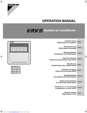
Daikin VRV III REYQ8PY1B Operation Manual (19 pages)
VRV III System
Brand:
Daikin
| Category:
Air Conditioner
| Size: 1.74 MB
Table of Contents
Operation Manual
1
Table of Contents
5
Safety Cautions
5
Specifications
7
What to Do before Operation
8
Remote Controller and Cool/Heat Selector: Name and Function of each Switch and Display
8
Operation Range
9
Operation Procedure
9
Optimum Operation
13
Seasonal Maintenance
13
Following Symptoms Are Not Air Conditioner Troubles
14
Trouble Shooting
16
Advertisement
Advertisement
Related Products
Daikin REYQ8P
Daikin REYQ8M7W1B
Daikin REYQ8P8Y1B
Daikin REYQ8T7Y1B
Daikin VRV II REYQ8M8W1B
Daikin REYQ384AATJ Series
Daikin REYQ408XBYC Series
Daikin VRV II REYQ48M
Daikin VRVIII REYQ240PBTJ
Daikin REYQ288XAYDU
Daikin Categories
Air Conditioner
Heat Pump
Remote Control
Chiller
Fan
More Daikin Manuals
Login
Sign In
OR
Sign in with Facebook
Sign in with Google
Upload manual
Upload from disk
Upload from URL