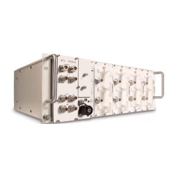
Sign In
Upload
Manuals
Brands
CommScope Manuals
Repeater
Node AM4
CommScope Node AM4 Manuals
Manuals and User Guides for CommScope Node AM4. We have
1
CommScope Node AM4 manual available for free PDF download: Manual
CommScope Node AM4 Manual (83 pages)
Node AM4 4 slots
Brand:
CommScope
| Category:
Repeater
| Size: 4.09 MB
Table of Contents
Table of Contents
3
1 General
7
Used Abbreviations
7
Health and Safety
8
Property Damage Warnings
8
Compliance
9
About Commscope
14
International Contact Addresses for Customer Support
15
2 Introduction
17
Purpose
17
The Node Am4 Repeater
17
Quick Start Checklist
18
3 Installation
19
Mechanical Installation
19
Health and Safety for Mechanical Installation
19
Property Damage Warnings for Mechanical Installation
19
Removal of Transport Protection Cover
20
Inch Rack Mounting of the Node AM4
20
RF Card Installation
22
Electrical Installation
23
Health and Safety for Electrical Installation
23
Property Damage Warnings for Electrical Installation
23
Grounding
24
Figure 3-1 Grounding Bolt
24
Interconnection Cabling
25
Connection of the Antenna Cables
25
Figure 3-2 Example for Interconnecting Cabling for a Node AM4
25
Figure 3-3 Front View of Node AM4 Antenna Connections (Combiner with Three Pairs of Band Ports)
26
Table 3-1 Description of Node AM4 Antenna Connectors
26
Cleaning Procedure for RF Cable Connectors
27
Antenna Cable Connector Assembly
30
Power Connection
31
Figure 3-4 DC Mains Connector, PIN Assignment
31
Figure 3-5 Mains Connector, Location
31
Table 3-3 Node AM4, Voltage Range & External Breaker
32
Connection to the Node am
33
Setting up the Local Connection
33
Setting up the Remote Connection
33
Figure 3-6 Connecting the CAT5 Cable to the Node am for the Local Connection
33
4 Functional Description
34
Architecture
34
Features
34
Digital Channel Filters
34
Frequency Hopping
35
Filter Types
35
Status Information
35
Alarm Forwarding
36
Components
36
Figure 4-3 Layout of a Node AM4 (Combiner with Three Pairs of Band Ports), Maximum Equipment
36
Multiband Combiner
37
Figure 4-4 Node AM4 3-Band Combiner (850-900, 1800, 2100 Mhz) with Three Pairs of Band Ports)
37
Figure 4-5 Node AM4 2-Band Combiner (800-900 and 1800-2100 Mhz) with Two Pairs of Band Ports
38
Digital Channel Modules (DCM) / RF Cards
39
Figure 4-6 Single-Band DCM, RF Card, Low / Medium Power (Left) and High Power with Additional DL Amplifier (Right)
39
Figure 4-7 Dual Band DCM, RF Card (Medium Power)
39
Dummy Card
40
Power Supply Unit
40
Figure 4-8 Dummy Card
40
Figure 4-9 Power Supply (DC/DC Type), Front and Back
40
User Interface Board (UI1 Board)
41
Figure 4-10 UI-Board for General Applications, Installed
41
External Alarms
42
Figure 4-11 UI-Board for General Applications, Top and Rear View
42
Figure 4-12 PIN Assignment
43
Figure 4-13 Schematics of External Alarm Clamps
43
Figure 4-14 External Cable Gland
44
Figure 4-15 Summary Alarm Relay
44
Summary Alarm
44
Figure 4-16 Relay Contacts, Alarm Condition
45
Figure 4-17 Schematics of Summary Alarm Clamps
45
Table 4-1 Pin Assignment of Relay Contacts
45
User Interface 2 Board with Optional Features
46
VSWR Module Option
46
Battery Backup Option
46
Figure 4-18 UI2 Board Kit, Layout
46
Figure 4-19 Position of UI2 Board and BBU
47
Optional Modems
48
Figure 4-20 Modem Installed, Exemplary
48
Figure 4-21 Cable from the Modem to the Multiband Combiner, Exemplary
49
Figure 4-22 Modem Kit HC25 / PHS8 / PLS8 Node AM, Schematic Wiring
49
Figure 4-23 Modem Kit MC88/TRM-5 Node AM, Schematic Wiring
50
Figure 4-24 UI1 Board, Position of Modem RS232 Connector
50
Figure 4-25 SIM-Card Drawer
50
Figure 4-26 Installation of Modem RV50X
51
5 Maintenance
52
General
52
Replacement of Components
52
Table 5-1 Specified Torques for Stainless Steel Screws
53
Table 5-4 Specified Standard Tolerances
54
Multiband Combiner
55
Modem / Battery
57
Figure 5-1 Installation of Modem Onto Adapter Kit
59
VSWR Module (Optional)
61
Figure 5-2 VSWR Module, Layout
61
Figure 5-3 VSWR Module, Position of RF Connectors
61
Status LED
62
Figure 5-4 Cover of UI-Card with Status LED
62
Figure 5-5 Status LED and Connection Cables
62
Power Supply
63
RF Card Exchange / Upgrade with Additional RF Cards
66
Fan Unit
67
Backside Type
67
Bottom Type
68
6 Illustrations
71
Cabinet Drawings Node am
71
Layout
71
Figure 6-1 Cabinet of a Node AM4 (Fan Unit Backside Type)
71
Figure 6-2 Layout of the Node AM4, Example
71
7 Specifications
72
Electrical Specifications
72
RF Card Options
72
Table 7-2 RF Card Options for USA, Single Band Cards
73
Bandwidths Available in UL and DL Per Rack (Single-Band Cards)
74
Bandwidths Available in UL and DL Per Dual-Band Card
75
Table 7-7 Filter Resources Allocation (up to 5 Mhz Wide), Example
76
Mechanical Specifications
77
Environmental and Safety Specification
77
Features
77
Modems
78
Hc25 / Phs8 / Pls8 / Mc88 / Trm-5
78
Wireless Router M!DGE (Racom)
78
8 Spare Parts List
79
9 Index
81
10 List of Changes
82
Advertisement
Advertisement
Related Products
COMMSCOPE Teletilt ATC200-LITE-USB
CommScope ASH
CommScope ADCP-90-326
CommScope SYSTIMAX AirSPEED AP541
CommScope SYSTIMAX AirSPEED AP542
CommScope ATC200-1000
CommScope ATC300-1000
CommScope ATC300-2000
CommScope miniRepeater 1918
CommScope miniRepeater 8518
CommScope Categories
Cables and connectors
Antenna
Network Hardware
Wireless Access Point
Enclosure
More CommScope Manuals
Login
Sign In
OR
Sign in with Facebook
Sign in with Google
Upload manual
Upload from disk
Upload from URL