Sign In
Upload
Manuals
Brands
CIGWELD Manuals
Welding System
TRANSTIG 300 AC/DC
CIGWELD TRANSTIG 300 AC/DC Manuals
Manuals and User Guides for CIGWELD TRANSTIG 300 AC/DC. We have
3
CIGWELD TRANSTIG 300 AC/DC manuals available for free PDF download: Service Manual, Operating Manual
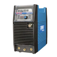
CIGWELD TRANSTIG 300 AC/DC Service Manual (134 pages)
INVERTER ARC
Brand:
CIGWELD
| Category:
Welding System
| Size: 7 MB
Table of Contents
Table of Contents
4
Arc Welding Safety Instructions and Warnings
9
Arc Welding Hazards
9
Principal Safety Standards
13
Declaration of Conformity
14
Introduction
15
How to Use this Manual
15
Equipment Identification
15
Receipt of Equipment
15
Symbol Chart
16
Description
17
Functional Block Diagrams
18
Transporting Methods
18
Specifications
19
Installation
21
Environment
21
Location
21
Electrical Input Connections
21
Mains Supply Voltage Requirements
22
High Frequency Introduction
23
High Frequency Interference
23
Duty Cycle
24
Operator Controls
25
Transtig 300 AC/DC Controls
25
Weld Process Selection for Transtig 300 AC/DC
27
Weld Parameter Descriptions for Transtig 300 AC/DC
28
Weld Parameters for Transtig 300 AC/DC
30
Power Source Features
31
Set-Up for Smaw (Stick) and Gtaw (Tig)
33
Sequence of Operation
35
Stick Welding
36
AC or DC HF TIG Welding
36
Slope Mode Sequence
37
Slope Mode with Repeat Sequence
37
Pulse Controls
38
Save-Load Operation
38
Section 7
39
Basic Tig Welding Guide
39
Explanation of "Fluttery Arc" When AC TIG Welding on Aluminum
39
Electrode Polarity
40
Tungsten Electrode Current Ranges
40
Tungsten Electrode Types
40
Guide for Selecting Filler Wire Diameter
41
Shielding Gas Selection
41
TIG Welding Parameters for Low Carbon & Low Alloy Steel Pipe
41
Welding Parameters for Aluminum
42
Welding Parameters for Steel
42
Section 8
43
Basic Arc Welding Guide
43
Electrode Polarity
43
Effects of Stick Welding Various Materials
43
Section 9
45
Routine Maintenance
45
Section 10
47
Basic Troubleshooting
47
TIG Welding Problems
47
Stick Welding Problems
50
Power Source Problems
53
Section 11
55
Voltage Reduction Device (Vrd)
55
VRD Specification
55
VRD Maintenance
55
Section 12
57
Power Source Error Codes
57
Section 13
61
Advanced Troubleshooting
61
System-Level Fault Isolation
61
Opening the Enclosure
61
Verification and Remedy to the Indicated Error Codes
63
E01 "Over-Temperature at the Primary Side
63
E02 "Over-Temperature at the Secondary Side
64
E03 "Transformer Over-Current Failure
64
E04 "Torch Cable Failure
65
E11 "Main Supply over Voltage
65
E12 "Main Supply under Voltage
65
E81 "Wrong Main Supply Voltage
65
E82 "Rated Voltage Selection Circuit Abnormality
66
E83 "Abnormalities in Mains Supply Voltage Detection
66
E85 "Pre-Charge Abnormality
66
E94 "Thermistor Malfunction
67
E99 "Initial Power Receiving
67
Verification and Remedy to Failures Without Indication Codes
67
Cooling Fan (FAN1) Failure" (Fan Is Not Rotating.)
67
Gas Valve Failure" (no Gas Flow through Unit)
68
No Weld Output
68
Operating Panel Failure
69
High Frequency Output Failure
69
Fault Isolation Tests
70
Preparation
70
Verification of the Power Input Circuitry
71
Verification of the AC Input Voltage Using an AC Voltmeter
71
Supply Voltage
72
Verification of the Cooling Fan, FAN1, Drive Circuitry
73
Verification of the Gas Valve, SOL1, Drive Circuitry
74
Verification of the Primary Diode (D1)
74
Verification of the Secondary Diode (D2-D7)
75
Verification of the Primary IGBT (Q1-Q24)
75
Verification of the Secondary IGBT (Q25-Q26)
76
Verification of No-Load Voltage (OCV)
76
Maintenance
79
Maintenance List
79
Service Tools
83
Tools and Parts
83
Notes of Disassembly and Assembly
83
Replacement Procedure
84
Pcb1 (Wk-5493)
84
Pcb2 (Wk-5597)
85
Pcb3 (Wk-5548), Pcb7 (Wk-5550)
86
Pcb4 (Wk-4819)
88
Pcb5 (Wk-5551)
88
Pcb6 (Wk-5449)
89
PCB8, PCB9 (WK-5479) and Q1-Q12 "Primary IGBT
89
PCB10, PCB11 (WK-5479) and Q13-Q24 "Primary IGBT
90
Pcb12 (Wk-5527)
90
Pcb13 (Wk-5528)
91
PCB14 (WK-5594) (T1-T2 "Main Trans Former")
92
Pcb15 (Wk-5606)
93
Pcb16 (Wk-5569)
94
Pcb17 (Wk-5570)
94
Pcb20 (Wk-5499)
95
Pcb21 (Wk-4917)
96
Pcb22 (Wk-5022)
97
Current Limiting Resistor (R6)
98
Discharge Resistor (R3)
98
Resistor (R7, R8)
99
Coupling Coil (CC1)
101
Inductor (FCH1)
101
Primary Thermistor (TH1)
102
Secondary Thermistor (TH2)
103
Cooling Fan (FAN1)
103
Solenoid Valve (SOL1)
104
Main ON/OFF Switch (S1)
105
Remote Socket (CON1)
106
High Freguency Unit (HF.UNIT1)
106
Hall Current Sensor (HCT1)
107
Primary Diode (D1)
108
Secondary Diode (D2-D7)
109
Secondary IGBT (Q25-Q26) and PCB18-PCB19
110
Current Trans (CT2, CT3)
111
Ring Core (L1)
112
Ring Core (L105)
114
Reactor (L101)
115
Reactor (L102)
116
Reactor (L103)
118
Appendix 1 Parts List
119
How to Use this Parts List
119
Appendix 2 Connection Wiring Guide
124
Appendix 3 Interconnect Diagram
126
Appendix 3: Transtig 300 Ac/DC Interconnect Diagram
128
Appendix 3: Transtig 300 Ac/DC Interconnect Diagram
128
Appendix 4 Diode Testing Basics
128
Appendix 5: Transtig 300 Ac/DC Options and Accessories
130
Appendix 5: Transtig 300 Ac/DC Options and Accessories
130
Cigweld Limited Warranty
130
Warranty Schedule - January 2008
133
Global Customer Service Contact Information
133
Advertisement
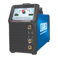
CIGWELD TRANSTIG 300 AC/DC Service Manual (104 pages)
Brand:
CIGWELD
| Category:
Welding System
| Size: 8 MB
Table of Contents
Service Manual
1
Welding Machine
1
Table of Contents
4
Arc Welding Safety Instructions and Warnings
7
Arc Welding Hazards
7
Principal Safety Standards
11
Servicing Hazards
12
EMF Information
14
Introduction
15
How to Use this Manual
15
Equipment Identification
15
Receipt of Equipment
15
Symbol Chart
16
Description
17
User Responsibility
17
Transporting Methods
17
Packaged Items
17
Installation, Operation and Setup
19
Duty Cycle
19
Specifications
20
Environment
21
Location
21
Ventilation
21
Mains Supply Voltage Requirements
21
Electromagnetic Compatibility
22
Operation
25
TRANSTIG 220AC/DC and 300AC/DC Power Source Controls, Indicators and Features
25
Setup for TIG (GTAW) Welding
32
TRANSTIG 220AC/DC and 300AC/DC - TIG (GTAW) Programming Mode
35
TIG (GTAW) Welding Secondary Parameters
40
GTAW Spot Welding Mode with DWELL Time (Stitch Mode)
41
Tip Tronic Operation
42
Setup for STICK (MMAW) Welding
44
TRANSTIG 220AC/DC and 300AC/DC- STICK (Mmaw)Programming Mode
46
User Specific Menus and Dead man Switch Mode
49
MMAW (STICK) Dead man Switch Mode
50
Special Function
52
Information Messages
55
Error Messages
56
Shielding Gas Regulator Operating Instructions
58
Foot Control, Part No. W4015800 (Optional Accessory)
61
Theory of OPERATION
63
Inverter Design
63
Section 5
63
Section 6
65
Troubleshooting
65
Basic Troubleshooting
65
Power Source Faults
66
Advanced Troubleshooting
67
Test Equipment and Tools for Troubleshooting and Servicing
68
Visually Inspect
68
Temperature Monitoring
69
Control Board Power Supply Monitoring
70
Main DC Bus Voltage Monitoring
71
Welding Output Voltage Monitoring
72
Remote Control Interface
73
Water Cooler Interface
74
Primary Supply Current Monitoring
74
TRANSTIG 220AC/DC PCB Connectors
75
TRANSTIG 300AC/DC PCB Connectors
81
Main Circuit Description
88
Section 7
91
Key Spare Parts
91
220AC/DC Power Source
91
300AC/DC Power Source
93
Appendix A: Circuit Diagram of 220Ac/DC
95
Appendix B: Circuit Diagram of 300Ac/DC
96
Appendix C: Optional Accessories
97
Global Customer Service Contact Information
103
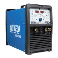
Cigweld TRANSTIG 300 AC/DC Operating Manual (70 pages)
200AC/DC Inverter arc welding machine
Brand:
Cigweld
| Category:
Welding System
| Size: 4 MB
Table of Contents
Table of Contents
4
Arc Welding Safety Instructions and Warnings
7
Arc Welding Hazards
7
Principal Safety Standards
11
Declaration of Conformity
12
Introduction
13
How to Use this Manual
13
Equipment Identification
13
Receipt of Equipment
13
Symbol Chart
14
Description
15
User Responsibility
15
Transporting Methods
15
Packaged Items
15
Duty Cycle
16
Specifications
17
Options and Accessories
18
Installation, Operation and Setup
19
Environment
19
Location
19
Ventilation
19
Mains Supply Voltage Requirements
19
High Frequency Introduction
19
High Frequency Interference
20
Electromagnetic Compatibility
20
WELDSKILL 200AC/DC Power Source Controls, Indicators and Features
22
WELDSKILL 200AC/DC - STICK Programming Mode
26
WELDSKILL 200AC/DC - LIFT TIG and HF TIG Programming Mode
28
Short Circuit Protection While Welding
31
Shielding Gas Regulator Operating Instructions
31
Setup for TIG (GTAW) Welding
33
Foot Control, Part No. W4015800 (Optional Accessory)
35
Setup for STICK (MMAW) Welding
37
Basic Welding Guide
39
Stick (MMAW) Basic Welding Technique
39
Stick (MMAW) Welding Troubleshooting
50
TIG (GTAW) Basic Welding Technique
52
TIG (GTAW) Welding Problems
54
Section 5
57
Power Source Problems and Routine Service Requirements
57
Basic Troubleshooting
57
Power Source Problems
57
Routine Service and Calibration Requirements
58
Cleaning the Welding Power Source
60
Section 6
61
Key Spare Parts
61
Power Source
61
Appendix: Circuit Diagram
63
Cigweld - Limited Warranty Terms
65
Advertisement
Advertisement
Related Products
Cigweld transarc 300 Si
CIGWELD 300Pi
CIGWELD 350i
CIGWELD WeldSkill 350 MIG
CIGWELD Transmig 330
CIGWELD Transmig 310
CIGWELD Transmig 355i
CIGWELD TRANSTIG 200 AC/DC
CIGWELD TRANSTIG 200
CIGWELD Transtig 220 AC/DC
CIGWELD Categories
Welding System
Wire Feeders
Inverter
More CIGWELD Manuals
Login
Sign In
OR
Sign in with Facebook
Sign in with Google
Upload manual
Upload from disk
Upload from URL