Sign In
Upload
Manuals
Brands
Carrier Manuals
Air Conditioner
GEMINI SELECT 38APS027
Carrier GEMINI SELECT 38APS027 Manuals
Manuals and User Guides for Carrier GEMINI SELECT 38APS027. We have
4
Carrier GEMINI SELECT 38APS027 manuals available for free PDF download: Manual, Operating And Service Manual, Installation Instructions Manual, Installation Instructions
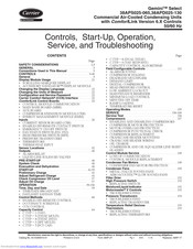
Carrier GEMINI SELECT 38APS027 Manual (243 pages)
Gemini Select, Commercial Air-Cooled Condensing Units with ComfortLink Version 6.X Controls 50/60 Hz
Brand:
Carrier
| Category:
Air Conditioner
| Size: 15.74 MB
Table of Contents
Table of Contents
1
Controls, Start-Up, Operation, Service, and Troubleshooting
1
Safety Considerations
2
General
3
Unit Sizes
3
Conventions Used in this Manual
3
Controls
3
Component, Power, and Control Drawings
4
Component Arrangement
5
Power Wiring Schematic
9
Power Wiring Schematic — 38APD040-060 (Typical)
11
Power Wiring Schematic — 38APS065 (Typical)
12
Power Wiring Schematic — 38APD070-100 (Typical)
13
Power Wiring Schematic — 38APD115,130 (Typical)
14
Control Wiring Schematic — 38APS025-050 (Typical)
15
Control Wiring Schematic — 38APD025-060 (Typical)
16
Control Wiring Schematic — 38APS065 (Typical)
17
Control Wiring Schematic — 38APD070-130 (Typical)
18
Non-Fused Disconnect
20
Terminal Block
20
Field Power Wiring
20
Display Module Usage
21
Accessory Navigator Display Module
21
Scrolling Marquee Display
21
(CCN) Interface
22
Carrier Comfort Network Interface
22
Changing the Display Language
22
Changing the Units of Measure
22
Configuration and Service Password
22
CCN Wiring Diagram
23
Comfortlink Control Boards
23
Aux Board (Aux)
24
Compressor Expansion Module (Cxb)
24
Main Base Board (Mbb)
24
Switch Number/Position
24
Aux Board
25
Energy Management Module (Emm)
26
Inputs
26
Emergency On/Off Switch
26
Enable/Off/Remote Contact Switch
26
Current Sensing Board (CSB) Input Connections
27
Switch Inputs
27
Emergency On/Off Switch
28
High Pressure Switch (Hps)
28
Pressure Transducer Identification
28
Pressure Transducers
28
Return Air Temperature (RAT)
28
Fan Status Switch (Fs1, Fs2)
29
Thermistors
29
HH79NZ041 Averaging Sensor
30
Supply Air Temperature (SAT)
30
Discharge Temperature Thermistor (DTT)
31
Outdoor-Air Temperature Sensor (OAT)
31
Return Gas Temperature (RGT)
31
Space Temperature Sensor (T55, T56)
31
Thermostat Input
32
Typical SPT Wiring
32
38APS025, 027, 030 Sensor Locations
33
Space Temperature Averaging
33
38APD025, 027, 030 Sensor Locations
34
38APS040, 050 Sensor Locations
34
38APD040, 050, 060 Sensor Locations
35
38APS065 Sensor Locations
35
38APD070 Sensor Locations
36
38APD070,080 Sensor Locations
36
38APD080, 090, 100 Sensor Locations
37
38APD090, 100 Sensor Locations
37
38APD115, 130 Sensor Locations
38
38APS065, 38APD070-130 OAT Location
39
Discharge Temperature Thermistor (DTT) Mounting
39
Outdoor Air Temperature (OAT) Thermistor Mounting
39
Sensor Locations
32
Outputs
40
Pre-Start-Up
40
System Check
40
Evacuation and Dehydration
40
Preliminary Puron Refrigerant (R-410A)
41
Start-Up
41
Preliminary Charge
41
Adjust Refrigerant Charge
41
Charging Chart — 38APD025
42
Charging Chart — 38APS025, 50/60 Hz
43
Charging Chart — 38APD027, 50/60 Hz
43
Charging Chart — 38APS027, 50/60 Hz
44
Charging Chart — 38APD030, 50/60 Hz
44
Charging Chart — 38APS030, 50/60 Hz
45
Charging Chart — 38APD040 — Circuit A, 50/60 Hz
45
Charging Chart — 38APD040
46
Charging Chart — 38APS040
46
Charging Chart — 38APD050
47
Charging Chart — 38APS050, 50/60 Hz
48
Charging Chart — 38APD060 — Circuit A, 50/60 Hz
48
38AP 60 Hz Additional Lubricant
57
Check Compressor Oil Level
57
Adjust Oil Charge
57
38AP 60 Hz Additional Lubricant (SI)
58
38AP 50 Hz Additional Lubricant (SI)
59
Operation
59
Time, Day, and Date
59
Time/Date Broadcast
59
Daylight Savings Time
59
Time Required Configuration
60
Day and Date Required Configurations
60
Broadcast Required Configurations
60
Daylight Savings Required Configurations
60
Control Methods
60
Enable-Off-Remote Control
60
Holiday Required Configurations
61
Local Schedule
61
Occupancy Schedule
61
Occupancy Schedule Required Configurations
62
CCN Global Schedule
63
CCN Global Schedule Required Configuration
63
Occupancy Schedule
63
Timed Override
63
Timed Override Required Configuration
63
Ccn Control
64
Hardware Requirements
64
Recommended Applications
64
Space Temperature Override Required Configuration
64
C.TYP=1 (VAV) Wiring
65
C.TYP=1 (VAV) Required Configuration
66
Space Temperature Control Mode Response for C.TYP=1 (VAV)
66
C.TYP=3 (Tstat Multi) Required Configuration
67
C.TYP=3 (Tstat Multi) Wiring
68
C.TYP=4 (Tstat 2 Stg) Required Configuration
69
Space Temperature Control Mode Response for C.TYP=3
69
C.TYP=4 (Tstat 2 Stg) Wiring
70
C.typ = 5 (Spt Multi
71
Space Temperature Control Mode Response for C.TYP=4
71
C.TYP=5 (SPT Multi) Required Configuration
72
C.TYP=5 (SPT Multi) Wiring
73
C-TYP=5, Space Temperature Control Example
74
Space Temperature Control Mode Response for C.TYP=5
75
C.TYP=7 (Pct Cap) Required Configuration
76
C.TYP=7 (Pct Cap) Wiring
76
Percent Capacity Vs. 4 to 20 Ma Signal
77
Space Temperature Control Mode Response for C.TYP=7
77
C.TYP=8 (Dual Tstat) Required Configuration
105
C.TYP=8 (Dual Tstat) Wiring
106
Space Temperature Control Mode Response for C.TYP=8
107
C.TYP=9 (VAV Setpoint) Required Configuration
108
Space Temperature Control Mode Response for C.TYP=9
108
C.TYP=9 (VAV Setpoint) Wiring
109
Active Setpoint
110
Active Setpoint (SI)
110
Capacity Control Algorithms
110
Supply Air Temperature Control
110
Capacity Control
64
Alarm Equipment Priority
111
Circuit Compressor Staging
112
Compressor Staging
112
Lead/Lag Determination (38APD Units)
112
Loading Sequence Select
112
Capacity Staging, Equal Circuit Loading
113
2-Stage Switch Controlled Demand Limit
115
Configuring 2-Stage Demand Limit
115
Deadband Multiplier
115
Demand Limit
115
4 To 20 Ma Demand Limit, Demand Limit Select DMDC=2
116
4-20 Ma Controlled Demand Limit
116
Configuring 4 to 20 Ma Demand Limit
116
CCN Controlled Demand Limit
117
CCN Loadshed Demand Limit
117
Digital Compressor Required Configurations
117
Digital Scroll Operation
117
Head Pressure Control
117
38APD,APS025-030 Fan Staging
118
Head Pressure Control Settings
118
38APD,APS040-050 Fan Staging
119
38APD060, 38APS065 Fan Staging
119
38APD070 Fan Staging
120
38APD080 Fan Staging
120
38APD090, 100 Fan Staging
121
38APD115 Fan Staging
123
38APD130 Fan Staging
124
Motormaster Required Configurations
125
Motormaster V Option/Accessory
125
Motormaster V Buttons and Mode Display
126
Motormaster V Connection Diagram
126
Motormaster V Terminal Block Designations
126
Run Jumper Connection Points
126
Motormaster V Program Parameters for Operating Modes
127
Changing Motormaster V Parameters
128
Configuring Maintenance Reminder
128
Configuring Minimum Load Control
128
Low Ambient Lockout
128
Minutes off Time
128
Ramp Loading
128
Configuring Ramp Loading Control
129
Configuring Space Temperature Reset
129
Space Temperature Reset
130
Configuring Outside Air Temperature Reset
131
Outside Air Temperature Reset
131
Configuring 4 to 20 Ma Temperature Reset
133
Thermostat Capacity Stage Control
111
Alarm Routing Control
111
Field Configurable Controls
111
Operating Modes
135
Temperature Reset
135
Service Test
136
Compressor Locations
137
Advanced Scroll Temperature Protection (ASTP)
138
Compressor Circuit Breakers
138
Compressor Motor Protection
138
Enabling and Disabling Compressors
138
Kriwan Motor Protection Module Troubleshooting
139
Motor Overload Protection
139
Recommended Minimum Cool down Time after Compressor Is Stopped
139
Kriwan Motor Protection Module Removal
140
Compressor Motor Sensor Harness Installation
141
Coresense Communication DIP Switch Settings for Kriwan Retrofit
141
Coresense Communication Module Mounting
141
Coresense Communications Motor Thermistor Plug
141
Coresense Communication Motor Protection Wiring
142
Coresense Communication Module DIP Switch Settings
143
Coresense Communication Module LED Flash Codes
143
Compressor Discharge Check Valve
144
Compressor Functional Check
144
Compressor Replacement
144
Compressor Fastener Recommended Torque Values
145
Compressor Junction Box with Motor Protection Module
145
Crankcase Heater Mounting
145
Digital Unloader Solenoid Valve
145
Crankcase Heater Color-Coded Tags
146
Crankcase Heater Location
146
Adding Oil
147
Factory/Recharge Oil Charge Quantity Per Compressor
147
Oil Charge
147
Typical Tandem Compressor Assembly
148
Typical Trio Compressor Assembly
148
Compressors
137
Oil Dip Tube Assemblies
149
Replacement Modules
149
Control Module Service
149
Condenser Fan Motors
149
Compressor and Oil Equalizer Line Sight
149
Loss of Communication
149
Condenser Fan Motor Protection
150
Value Fan Mounted Position
150
Metal (Value Sound) Fans
150
Aeroacoustic™ (Low Sound) Fans
150
Aeroacoustic Fan (Gray Bolt) Mounted Position
151
Aeroacoustic Fan (Black Bolt) Fan Hub Keyway
151
Aeroacoustic Fan (Black Bolt) Fan Motor Keyway
151
Aeroacoustic Fan (Black Bolt) Mounted Position
151
Motormaster V Controls
152
Filter Drier
152
Replacing Switch
152
High Pressure Switch
152
Moisture/Liquid Indicator
152
Motormaster V Fault Codes
154
Pressure Transducers
154
Replacing Transducer
155
Typical AUX Board (AUX) Thermistor Connections
155
Typical Main Base Board (MBB) Thermistor Connections
155
Outdoor Air Thermistor (OAT)
156
Replacing Thermistors
156
Return Gas Thermistor (RGT)
156
Thermistor Well Assembly
156
5K Thermistor Temperatures (F) Vs. Resistance/Voltage Drop
157
10K Thermistor Temperature Vs. Resistance/Voltage Drop
159
86K Thermistor Temperatures Vs. Resistance
160
Typical 38AP Pressure Transducer Wiring
155
Temperature Relief Devices
155
Recommended Maintenance Schedule
161
Lubrication
161
Navigator
161
Display Module
161
Refrigeration Circuit
161
Condenser Fan Blades
161
Condenser Fan Motor Bearings
161
Door Hinges
161
Recommendations
161
Ground Fault Interrupter-Convenience Outlet
161
Troubleshooting
162
Alarms and Alerts
162
Resetting Alarms
162
Alarm History
162
Alarm and Alert Codes
163
Alarm and Alert Details
166
Communication Failure
166
T073 — Outside Air Thermistor Failure
167
T074 — Space Temperature Thermistor Failure
167
T082 — Space Temperature Offset Sensor Failure
167
T094 — Discharge Gas Thermistor Failure
167
A140 — Reverse Rotation Detected
171
Maximum Saturated Condensing Temperature
171
Reverse Rotation Detection (Psig)
172
Reverse Rotation Detection (Kpa)
172
Illegal Configurations (Alarm A151)
173
A150 — Unit Is in Emergency Stop
173
A151 — Illegal Configuration Alarm
173
A152 — Unit down Due to Failure
174
T153 — Real Time Clock Hardware Failure Alert
174
A154 — Serial EEPROM Hardware Failure
174
T155 — Serial EEPROM Storage Failure
174
A175 — Loss of Communication with AUX Board
175
T176 — 4 to 20 Ma Reset Input Failure
175
T177 — 4 to 20 Ma Demand Limit Input Failure
175
T303 — Coil - Scheduled Maintenance Due
175
Scrolling Marquee Display Menu Structure
176
Appendix A - Display Tables
176
Run Status Mode and Sub-Mode Directory
177
Service Test Mode and Sub-Mode Directory
178
Temperatures Mode and Sub-Mode Directory
179
Pressures Mode and Sub-Mode Directory
179
Setpoints Mode and Sub-Mode Directory
180
Inputs Mode and Sub-Mode Directory
181
Outputs Mode and Sub-Mode Directory
181
Configuration Mode and Sub-Mode Directory
182
Configuration UNIT Data
185
Time Clock Mode and Sub-Mode Directory
186
Operating Mode and Sub-Mode Directory
194
Alarms Mode and Sub-Mode Directory
194
Status Tables
195
Appendix B - Ccn Tables
195
Maintenance Tables
198
Configuration Tables
202
DISPLAY (Marquee Display Set Up)
202
Service Table
208
Setpoint Table
208
Time Schedule Tables
209
Bacnet Communication Option
210
Address Rotary Switches
210
UPC Open Controller
210
To Address the Upc Open Controller
210
Configuring the Bas Port for Bacnet Ms/Tp
211
SW3 Protocol Switch Settings for MS/TP
211
Baud Selection Table
211
UPC Open Controller DIP Switches
211
Appendix C - Bacnet Communication
211
BT485 Terminator Installation
212
MS/TP Wiring Recommendations
212
Local Access to the Upc Open Controller
213
Configuring the Upc Open Controller's Properties
213
Open System Wiring Specifications and Recommended Vendors
213
Bacview Device Connection
213
LED Status Indicators
214
Run and Error Leds Controller and Network Status Indication
214
Communication Leds
214
Network Points List
215
Piping and Instrumentation Diagrams
219
38APD025-030 Piping and Instrumentation
219
38APD040-060 Piping and Instrumentation
220
Appendix D - Piping and Instrumentation
220
38APD070,080 Piping and Instrumentation
221
38APD090-130 Piping and Instrumentation
222
38APS025-030 Piping and Instrumentation
223
38APS040-050 Piping and Instrumentation
223
38APS065 Piping and Instrumentation
224
Control Methods with Inputs for Control Mode Comparison
225
Appendix E - Control Methods with Inputs for Control Mode
226
Index
227
Preliminary Equipment Check
230
Air-Handling Unit
231
System Start-Up
233
Pre-Start Check
233
Start and Operate the System
234
Advertisement
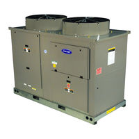
Carrier GEMINI SELECT 38APS027 Operating And Service Manual (92 pages)
Commercial Air-Cooled Condensing Units with COMFORTLINK Controls 50/60 Hz
Brand:
Carrier
| Category:
Air Conditioner
| Size: 6.68 MB
Table of Contents
Table of Contents
1
Safety Considerations
1
General
2
Controls
2
Conventions Used in this Manual
2
Display Module Usage
17
Scrolling Marquee Display
17
Accessory Navigator™ Display Module
17
Main Base Board (MBB)
18
Current Sensor Board (CSB)
18
Energy Management Module (EMM)
18
Compressor Expansion Module (CXB)
19
AUX Board (AUX)
19
Enable/Off/Remote Contact Switch
19
Emergency On/Off Switch
19
Board Addresses
19
Control Module Communication
19
Carrier Comfort Network (CCN) Interface
20
Operating Data
20
Sensors
20
Return Air Temperature (Rat) Accessory
20
Supply Air Temperature (Sat) Accessory
21
Compressor Return Gas Temperature
21
Sensor (Rgt)
21
Outdoor-Air Temperature Sensor (Oat)
21
Discharge Temperature Thermistor (Dtt)
21
Space Temperature Sensor (Spt)
21
Fan Status Input
23
Thermostat Input
23
Pressure Transducer Inputs
23
Energy Management Module
23
Control
23
Head Pressure Control
26
Service Test
28
Operating Modes
28
Operation of Machine Based on Control
28
Method
28
Set Point Adjustment
29
Demand Limit
31
DEMAND LIMIT (2-Stage Switch Controlled)
31
Externally Powered Demand Limit
31
DEMAND LIMIT (CCN Loadshed Controlled)
32
Cooling Set Point (4 to 20 Ma)
32
Digital Scroll Option
32
Pre-Start-Up
33
System Check
33
Start-Up
33
Preliminary Charge
33
Adjust Refrigerant Charge
34
Check Compressor Oil Level
47
Final Checks
47
Oil Charge
47
Actual Start-Up
47
Operation
48
Operating Limitations
48
Voltage (All Units)
48
Operation Sequence
48
Service
49
Electronic Components
49
Thermistors
49
Pressure Transducers
54
Condenser Fans
54
Controller
54
Drive Programming
55
Loss of Ccn Communications
55
Compressors
59
Maintenance
59
Recommended Maintenance Schedule
59
Maintenance
60
Microchannel Heat Exchanger (MCHX) Condenser Coil Maintenance and Cleaning
60
Recommendations
60
Troubleshooting
60
Complete Unit Stoppage and Restart
60
Unit Enable-Off-Remote Contact Switch Is off
60
Open 24-V Control Circuit Breaker(S)
60
Diagnostic Alert Codes and Possible Causes
61
Advanced Scroll Temperature Protection Label
61
Alarms and Alerts
61
Alarm and Alert Codes
64
Example of Reading and Clearing Alarms
66
Appendix A - Display Tables
67
Appendix B - Ccn Tables
79
Condensing Unit
87
Carrier GEMINI SELECT 38APS027 Installation Instructions Manual (36 pages)
Air-Cooled Condensing Units with PURON Refrigerant (R-410A) 50/60 Hz
Brand:
Carrier
| Category:
Air Conditioner
| Size: 5.45 MB
Table of Contents
Installation Instructions
1
Installation
2
Domestic Units
2
Export Units
2
Placing Units
2
Connections
17
Size Refrigerant Lines
17
Liquid Line Solenoid Valve
17
Step 4 — Make Electrical Connections
26
Power Supply
26
Power Wiring
26
Control Power
26
Field Control Wiring
26
Return Air
27
Outside Air
27
Evaporator Coil
27
Step 5 — Install Accessories
34
Advertisement
Carrier GEMINI SELECT 38APS027 Installation Instructions (4 pages)
Long Line Check Valve Accessory
Brand:
Carrier
| Category:
Air Conditioner Accessories
| Size: 2.9 MB
Advertisement
Related Products
Carrier GEMINI SELECT 38APS025-065
Carrier GEMINI SELECT 38APS025-050
Carrier GEMINI SELECT 38APS025
Carrier GEMINI SELECT 38APS030
Carrier GEMINI SELECT 38APS040
Carrier GEMINI SELECT 38APS050
Carrier 38APS065
Carrier GEMINI SELECT 38APD030
Carrier 38APD115
Carrier GEMINI SELECT 38APD100
Carrier Categories
Air Conditioner
Heat Pump
Furnace
Thermostat
Chiller
More Carrier Manuals
Login
Sign In
OR
Sign in with Facebook
Sign in with Google
Upload manual
Upload from disk
Upload from URL