Sign In
Upload
Manuals
Brands
Campbell Manuals
Measuring Instruments
CR800 Series
User Manuals: Campbell CR800 Series Control Datalogger
Manuals and User Guides for Campbell CR800 Series Control Datalogger. We have
2
Campbell CR800 Series Control Datalogger manuals available for free PDF download: Operator's Manual
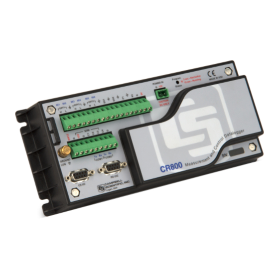
Campbell CR800 Series Operator's Manual (566 pages)
Measurement and Control System
Brand:
Campbell
| Category:
Measuring Instruments
| Size: 24 MB
Table of Contents
About this Manual
5
Table of Contents
7
C Rbasic Example 42. Using Trigvar to Trigger Data Storage 2
24
Section 1. Introduction
27
Hello
27
Typography
27
Section 2. Cautionary Statements
29
Section 3. Initial Inspection
31
Section 4. Quickstart Tutorial
33
Primer - CR800 Data-Acquisition
33
Components of a Data-Acquisition System
33
Data Retrieval
33
Datalogger
33
Sensors
33
CR800 Module and Power Supply
34
Figure 1: Data-Acquisition System Components
34
Wiring Panel
34
Figure 2: Wiring Panel
35
Backup Battery
36
Power Supply
36
Sensors
36
Analog Sensors
36
Figure 3: Analog Sensor Wired to Single-Ended Channel #1
36
Bridge Sensors
37
Figure 4: Analog Sensor Wired to Differential Channel #1
37
Table 1. Single-Ended and Differential Input Channels
37
Voltage Excitation
37
Figure 5: Half-Bridge Wiring -- Wind Vane Potentiometer
38
Figure 6: Full-Bridge Wiring -- Pressure Transducer
38
Pulse Sensors
38
Figure 7: Pulse-Sensor Output Signal Types
39
Pulse-Input Channels
39
Pulses Measured
39
Table 2. Pulse-Input Channels and Measurements
39
Figure 8: Pulse-Input Wiring -- Anemometer Switch
40
Pulse Sensor Wiring
40
RS-232 Sensors
40
Sensors
40
Figure 10: Use of RS-232 and Digital I/O When Reading RS-232 Devices
41
Figure 9: Location of RS-232 Ports
41
Digital I/O Ports
42
SDM Channels
42
Input Expansion Modules
42
Figure 11: Control and Monitoring with Digital I/O
42
List of Figures
34
List of Tables
37
Hands-On: Measuring a Thermocouple
43
What You will Need
43
Hardware Setup
43
External Power Supply
43
PC200W Software Setup
44
Figure 12: Power and RS-232 Connections
44
Figure 13: PC200W Main Window
45
Table 3. PC200W Ezsetup Wizard Example Selections
45
Write Program with Short Cut
46
Procedure: (Short Cut Steps 1 to 6)
46
Figure 14: Short Cut Temperature Sensor Folder
47
Procedure: (Short Cut Steps 7 to 9)
47
Figure 15: Short Cut Thermocouple Wiring
48
Procedure: (Short Cut Steps 10 to 11)
48
Figure 16: Short Cut Outputs Tab
49
Procedure: (Short Cut Steps 12 to 16)
49
Figure 17: Short Cut Output Table Definition
50
Figure 18: Short Cut Compile Confirmation
50
Procedure: (Short Cut Step 17 to 18)
50
Send Program and Collect Data
51
Figure 19: PC200W Connect Button
51
Procedure: (PC200W Step 1)
51
Procedure: (PC200W Steps 2 to 4)
51
Figure 20: PC200W Monitor Data Tab – Public Table
52
Figure 21: PC200W Monitor Data Tab – Public Table
52
Figure 22: PC200W Monitor Data Tab – Public and Onemin Tables
53
Procedure: (PC200W Step 5)
53
Figure 23: PC200W Collect Data Tab
54
Procedure: (PC200W Step 6)
54
Procedure: (PC200W Steps 7 to 9)
54
Figure 24: PC200W View Data Utility
55
Figure 25: PC200W View Data Table
56
Figure 26: PC200W View Line Graph
56
Procedure: (PC200W Steps 10 to 11)
56
Procedure: (PC200W Steps 12 to 13)
56
Section 5. System Overview
57
CR800 Datalogger
58
Figure 27: Features of a Data-Acquisition System
58
Clock
59
Sensor Support
59
CR800 Wiring Panel
60
Measurement Inputs
60
Voltage Outputs
61
Grounding Terminals
62
Power in
62
Power out
62
Power Terminals
62
Communications Ports
63
Integrated Keyboard Display
63
CR1000KD Keyboard Display
64
Power Requirements
64
Programming
65
Operating System and Settings
65
User Programming
65
Memory and Final Data Storage
66
Data Retrieval
67
Data File-Formats in CR800 Memory
67
Via Mass-Storage Device
67
Via Telecommunications
67
Data Format on Computer
68
Communications
68
Pakbus
68
Custom Menus
69
DNP3 Communication
69
Keyboard Display
69
Modbus
69
Security
70
Figure 28: Custom Menu Example
70
Vulnerabilities
71
Pass-Code Lockout
72
Csipasswd
73
Passwords
73
Security By-Pass
73
File Encryption
74
IS Instructions
74
Pakbus Instructions
74
Settings
74
Communications Encryption
75
Hiding Files
75
Signatures
75
Maintenance
75
Protection from Voltage Transients
75
Protection from Water
75
Calibration
76
Internal Battery
76
Datalogger Support Software
76
Section 6. CR800 Specifications
79
Section 7. Installation
81
Moisture Protection
81
Temperature Range
81
Enclosures
81
Power Sources
82
Figure 29: Enclosure
82
Calculating Power Consumption
83
External Batteries
83
Power Supplies
83
CR800 Power Requirement
83
Vehicle Power Connections
83
Figure 30: Connecting to Vehicle Power Supply
84
Table 4. Current Source and Sink Limits
84
Continuous Regulated (5 Volt)
85
Switched Voltage Excitation
85
Continuous Unregulated (Nominal 12 Volt)
86
Grounding
86
Switched Unregulated (Nominal 12 Volt)
86
Powering Sensors and Devices
84
ESD Protection
86
Figure 31: Schematic of Grounds
88
Lightning Protection
88
Figure 32: Lightning-Protection Scheme
89
Ground Potential Differences
90
External Signal Conditioner
90
Soil Temperature Thermocouple
90
Single-Ended Measurement Reference
90
Ground Looping in Ionic Measurements
91
CR800 Configuration
92
Device Configuration Utility
92
Figure 33: Model of a Ground Loop with a Resistive Sensor
92
Figure 34: Device Configuration Utility (Devconfig)
93
Sending the Operating System
94
Sending os with Devconfig
94
Figure 35: Devconfig os Download Window
95
Figure 36: Dialog Box Confirming os Download
95
Sending os with External Memory
96
Sending os with Program Send
96
Settings
96
Settings Via Devconfig
96
Table 5. Operating System Version in Which Preserve Settings Via Program Send Instituted
96
Figure 37: Devconfig Settings Editor
97
Deployment Tab
98
Figure 38: Summary of CR800 Configuration
98
Figure 39: Devconfig Deployment Tab
98
Figure 40: Devconfig Deployment | Comports Settings Tab
100
Figure 41: Devconfig Deployment | Advanced Tab
101
Logger Control Tab
101
Figure 42: Devconfig Logger Control Tab
102
Settings Via Crbasic
102
Durable Settings
103
Include" File
103
Figure 43: "Include File" Settings Via Devconfig
104
Figure 44: "Include File" Settings Via Pakbusgraph
104
Default.cr8 File
105
Program Run Priorities
106
Figure 45: Network Planner Setup
107
Network Planner
107
Overview
107
Basics
108
Programming
108
Writing and Editing Programs
108
Short Cut Editor and Program Generator
108
Crbasic Editor
109
Inserting Comments into Program
109
Sending Programs
110
Preserving Data at Program Send
110
Figure 46: Crbasic Editor Program Send File Control Window
111
Table 6. Program Send Options that Reset Memory
111
Table 7. Data Table Structures
111
Syntax
112
Numerical Formats
112
Table 8. Formats for Entering Numbers in Crbasic
112
Table 9. Crbasic Program Structure
113
Command Line
115
Multiple Statements on One Line
115
One Statement on Multiple Lines
115
Single-Line Declarations
116
Variables
116
Table 10. Data Types
119
Constants
122
Table 11. Predefined Constants and Reserved Words
123
Alias and Unit Declarations
124
Data Tables
125
Declared Sequences
125
Table 12. TOA5 Environment Line
126
Table 13. Typical Data Table
127
Table 14. Datainterval() Lapse Parameter Options
130
Subroutines
131
Execution and Task Priority
132
Incidental Sequences
132
Pipeline Mode
133
Table 15. Task Processes
133
Sequential Mode
134
Table 16. Pipeline Mode Task Priorities
134
Execution Timing
135
Scan() / Nextscan
135
Table 17. Program Timing Instructions
135
Slowsequence / Endsequence
136
Scan Priorities in Sequential Mode
137
Subscan() / Nextsubscan
137
Figure 47: Sequential-Mode Scan Priority Flow Diagrams
139
Instructions
139
Measurement and Data-Storage Processing
139
Argument Types
140
Names in Arguments
140
Table 18. Rules for Names
140
Arrays of Multipliers and Offsets
141
Expressions in Arguments
141
Expressions
142
Expressions with Numeric Data Types
143
Floating-Point Arithmetic
143
Mathematical Operations
143
Logical Expressions
145
Table 19. Binary Conditions of TRUE and FALSE
146
String Expressions
147
Table 20. Logical Expression Examples
147
Program Access to Data Tables
148
Table 21. Abbreviations of Names of Data Processes
149
System Signatures
150
Tips
150
Use of Variable Arrays to Conserve Code Space
150
Use of Move() to Conserve Code Space
151
Programming Resource Library
151
Calibration Using Fieldcal() and Fieldcalstrain()
151
CAL Files
151
Calibration Wizard Overview
152
Crbasic Programming
152
Manual Calibration Overview
152
Single-Point Calibrations (Zero, Offset, or Zero Basis)
153
Two-Point Calibrations (Multiplier / Gain)
153
Fieldcal() Demonstration Programs
154
Table 22. Calibration Report for Air RH Sensor
154
Zero or Tare (Option 0)
154
Figure 48: Zero (Option 0)
155
Offset (Option 1)
156
Table 23. Calibration Report for Salinity Sensor
156
Zero Basis (Option 4)
157
Table 24. Calibration Report for Flow Meter
159
Two-Point Slope and Offset (Option 2)
159
Two-Point Slope Only (Option 3)
161
Fieldcalstrain() Demonstration Program
162
Figure 49: Quarter-Bridge Strain-Gage Schematic with RC-Resistor Shunt
164
Quarter-Bridge Shunt (Option 13)
165
Figure 50: Strain-Gage Shunt Calibration Started
166
Figure 51: Strain-Gage Shunt Calibration Finished
166
Figure 52: Starting Zero Procedure
166
Quarter-Bridge Zero (Option 10)
166
Information Services
167
Figure 53: Zero Procedure Finished
167
Default HTTP Web Server
168
Pakbus over TCP/IP and Callback
168
Custom HTTP Web Server
169
Figure 54: Preconfigured HTML Home
169
Figure 55: Home Page Created Using Webpagebegin() Instruction
170
Figure 56: Customized Numeric-Monitor Web
170
FTP Client
172
FTP Server
172
Ping
172
Snmp
172
Telnet
172
Dhcp
173
Dns
173
Micro-Serial Server
173
Modbus TCP/IP
173
Smtp
173
Sensor Support
173
Figure 57: Entering SDI-12 Transparent Mode
174
Transparent Mode
174
Table 25. Standard SDI-12 Command and Response Set
175
Transparent Mode Commands
175
Programmed Modes
178
Recorder Mode
178
Table 26. Sdi12Recorder() Commands
179
Sensor Mode
185
Power Considerations
186
Table 27. SDI-12 Sensor Setup -- Results
186
Table 28. Example Power Usage Profile for a Network of SDI-12 Probes
187
Subroutines
188
Wind Vector
189
Outputopt Parameters
190
Table 29. Outputopt Options
190
Wind Vector Processing
190
Calculations
191
Measured Raw Data
191
Figure 58: Mean Wind-Vector Graph
192
Figure 59: Standard Deviation of Direction
193
Custom Menus
194
Figure 60: Custom Menu Example — Home Screen
195
Figure 61: Custom Menu Example — View-Data Window
195
Figure 62: Custom Menu Example — Make-Notes Sub Menu
195
Figure 63: Custom Menu Example — Predefined-Notes Pick List
196
Figure 64: Custom Menu Example — Free-Entry Notes Window
196
Figure 65: Custom Menu Example — Accept / Clear Notes Window
196
Figure 66: Custom Menu Example — Control Sub Menu
196
Figure 67: Custom Menu Example — Control-LED Pick List
197
Figure 68: Custom Menu Example — Control-LED Boolean Pick List
197
Conditional Compilation
199
Serial I/O
201
Introduction
202
Table 30. ASCII / ANSI Equivalents
202
I/O Ports
203
Protocols
203
Table 31. CR800 Serial Ports
203
Glossary of Terms
204
Crbasic Programming
205
Input Instruction Set Basics
206
Input Programming Basics
207
Output Programming Basics
208
Translating Bytes
209
Memory Considerations
210
Demonstration Program
211
Configure Hyperterminal
212
Testing Applications
212
Figure 69: Hyperterminal New Connection Description
213
Figure 70: Hyperterminal Connect-To Settings
213
Figure 71: Hyperterminal COM-Port Settings Tab
214
Figure 72: Hyperterminal ASCII Setup
214
Create Send Text File
215
Create Text-Capture File
215
Figure 73: Hyperterminal Send Text-File Example
215
Figure 74: Hyperterminal Text-Capture File Example
215
Serial Input Test Program
215
Q & a
221
Trigvar and Disablevar - Controlling Data Output and Processing
223
NSEC Data Type
224
Figure 75: Data from Trigvar Program
224
NSEC Options
225
Bool8 Data Type
228
Figure 76: Alarms Toggled in Bit-Shift Example
229
Figure 77: Bool8 Data from Bit-Shift Example (Numeric Monitor)
229
Figure 78: Bool8 Data from Bit-Shift Example (PC Data File)
230
Faster Measurement Rates
232
Measurements from 1 Hz to 100 Hz
233
Table 32. TABLE. Summary of Analog Voltage Measurement Rates
233
Table 33. Measuring Voltse() at 1 Hz
233
Measurement Rate: 101 to 600 Hz
234
Table 34. Crbasic EXAMPLE. Measuring Voltse() at 100 Hz
234
Table 35. Measuring Voltse() at 200 Hz
234
Subscan() / Nextsubscan Details
235
Measurement Rate: 601 to 2000 Hz
236
Table 36. Measuring Voltse() at 2000 Hz
236
String Operations
237
Table 37. Parameters for Analog Burst Mode (601 to 2000 Hz)
237
String Operators
238
Table 38. String Operators
238
String Concatenation
239
String NULL Character
239
Table 39. String Concatenation Examples
239
Table 40. String NULL Character Examples
239
Extracting String Characters
240
Inserting String Characters
240
String Use of ASCII / ANSII Codes
240
Table 41. Extracting String Characters
240
Table 42. Use of ASCII / ANSII Codes Examples
240
Data Tables
241
Formatting String Hexadecimal Variables
241
Formatting Strings
241
Table 43. Formatting Strings Examples
241
Table 44. Formatting Hexadecimal Variables - Examples
241
Pulsecountreset Instruction
242
Program Signatures
243
Binary Runtime Signature
243
Executable Code Signatures
243
Text Signature
243
Advanced Programming Examples
244
Miscellaneous Features
244
Running Average and Total of Rain
247
Use of Multiple Scans
247
Groundwater Pump Test
248
Scaling Array
251
Conditional Output
252
Capturing Events
253
PRT Measurement
254
PRT Calculation Standards
254
Table 45. Prtcalc() Type-Code-1 Sensor
255
Table 46. Prtcalc() Type-Code-2 Sensor
256
Table 47. Prtcalc() Type-Code-3 Sensor
256
Table 48. Prtcalc() Type-Code-4 Sensor
257
Table 49. Prtcalc() Type-Code-5 Sensor
257
Measuring Pt100S (100-Ohm Prts)
258
PT100 in Four-Wire Half-Bridge
258
Self-Heating and Resolution
258
Table 50. Prtcalc() Type-Code-6 Sensor
258
Figure 79: PT100 in Four-Wire Half-Bridge
260
PT100 in Three-Wire Half-Bridge
260
Figure 80: PT100 in Three-Wire Half-Bridge
261
PT100 in Four-Wire Full-Bridge
262
Figure 81: PT100 in Four-Wire Full-Bridge
263
Figure 82: Running-Average Equation
264
Running Average
264
Figure 83: Running-Average Frequency Response
266
Figure 84: Running-Average Signal Attenuation
267
Measurements
269
Time
269
Time Stamps
269
Advertisement
Campbell CR800 Series Operator's Manual (598 pages)
Brand:
Campbell
| Category:
Data Loggers
| Size: 23 MB
Table of Contents
Table of Contents
9
1 Introduction
29
Hello
29
Typography
30
Capturing Crbasic Code
30
2 Precautions
31
3 Initial Inspection
33
4 Quickstart
35
Sensors - Quickstart
35
Datalogger - Quickstart
36
CR800 Module
36
Wiring Panel - Quickstart
36
Power Supplies - Quickstart
37
Internal Battery - Quickstart
38
Data Retrieval and Comms - Quickstart
38
Datalogger Support Software - Quickstart
39
Tutorial: Measuring a Thermocouple
39
What You will Need
40
Hardware Setup
40
Connect External Power Supply
40
Connect Comms
41
PC200W Software Setup
41
FIGURE 2: Connect Power and Comms
41
FIGURE 3: PC200W Main Window
42
Write Crbasic Program with Short Cut
43
PC200W Ezsetup Wizard Prompts
43
Procedure: (Short Cut Steps 1 to 5)
44
FIGURE 4: Short Cut Temperature Sensor Folder
44
Procedure: (Short Cut Steps 6 to 7)
45
Procedure: (Short Cut Step 8)
45
Procedure: (Short Cut Steps 9 to 12)
45
FIGURE 5: Short Cut Outputs Tab
45
Procedure: (Short Cut Steps 13 to 14)
46
Send Program and Collect Data
46
FIGURE 6: Short Cut Compile Confirmation Window and Results Tab
46
FIGURE 7: PC200W Main Window
47
Procedure: (PC200W Step 1)
47
Procedure: (PC200W Steps 2 to 4)
47
FIGURE 8: PC200W Monitor Data Tab - Public Table
48
Procedure: (PC200W Step 5)
48
FIGURE 10: PC200W Collect Data Tab
49
FIGURE 9: PC200W Monitor Data Tab - Public and Onemin Tables
49
Procedure: (PC200W Step 6)
49
FIGURE 11: PC200W View Data Utility
50
Procedure: (PC200W Steps 7 to 10)
50
FIGURE 12: PC200W View Data Table
51
Procedure: (PC200W Steps 11 to 12)
51
Procedure: (PC200W Steps 13 to 14)
51
Data Acquisition Systems - Quickstart
52
FIGURE 13: PC200W View Line Graph
52
FIGURE 14: Data-Acquisition System Components
53
5 Overview
55
Datalogger - Overview
56
FIGURE 15: Data Acquisition System - Overview
56
Wiring Panel - Overview
57
FIGURE 16: Wiring Panel
58
FIGURE 1: Wiring Panel
58
CR800 Wiring Panel Terminal Definitions
58
Switched Voltage Output - Overview
59
Voltage Excitation - Overview
60
FIGURE 17: Control and Monitoring with C Terminals
60
Power Terminals
61
Communication Ports - Overview
61
Power in Terminals
61
Power out Terminals
61
Ports
62
CPI Port and CDM Devices - Overview
63
Ports
63
SDM Port
63
Ethernet Port
64
Grounding - Overview
64
Measurements - Overview
64
Analog Measurements - Overview
65
Time Keeping - Overview
65
Voltage Measurements - Overview
65
FIGURE 18: Analog Sensor Wired to Single-Ended Channel #1
66
FIGURE 19: Analog Sensor Wired to Differential Channel #1
67
Single-Ended Measurements - Overview
67
Current Measurements - Overview
68
Differential Measurements - Overview
68
FIGURE 20: Half-Bridge Wiring Example - Wind Vane Potentiometer
69
Resistance Measurements - Overview
69
Voltage Excitation
69
FIGURE 21: Full-Bridge Wiring Example - Pressure Transducer
70
Pulse Measurements - Overview
70
Strain Measurements - Overview
70
FIGURE 22: Pulse Sensor Output Signal Types
71
Pulse Input Channels
71
Pulses Measured
71
FIGURE 23: Pulse Input Wiring Example - Anemometer
72
Pulse Sensor Wiring
72
Pulse Input Terminals and Measurements
72
Period Averaging - Overview
73
Vibrating Wire Measurements - Overview
73
Reading Smart Sensors - Overview
74
Sensor Support - Overview
74
Field Calibration - Overview
75
FIGURE 24: Terminals Configurable for RS-232 Input
75
FIGURE 25: Use of RS-232 and Digital I/O When Reading
75
Overview
75
RS-232 — Overview
75
Cabling Effects - Overview
76
Synchronizing Measurements - Overview
76
Synchronizing Measurements in a Datalogger Network - Overview
76
Synchronizing Measurements in the CR800 - Overview
76
Data Retrieval and Comms - Overview
76
Comms Protocols
77
Data File Formats in CR800 Memory
77
Data Format on Computer
77
Mass-Storage Device
77
Pakbus Comms - Overview
77
Alternate Comms Protocols - Overview
78
Modbus - Overview
78
DNP3 - Overview
79
TCP/IP - Overview
79
Comms Hardware - Overview
80
Keyboard/Display - Overview
80
Character Set
81
FIGURE 26: CR1000KD Keyboard/Display
81
Integrated/Keyboard Display
81
Custom Menus - Overview
82
Measurement and Control Peripherals - Overview
82
FIGURE 27: Custom Menu Example
82
Power Supplies - Overview
83
CR800 Setup - Overview
83
Crbasic Programming - Overview
84
Security - Overview
84
Maintenance - Overview
85
Protection from Moisture - Overview
85
Protection from Voltage Transients - Overview
85
Factory Calibration - Overview
86
Internal Battery - Overview
86
Datalogger Support Software - Overview
86
PLC Control - Overview
87
Auto Self-Calibration - Overview
89
Memory - Overview
89
6 Specifications
91
7 Installation
93
Enclosures - Details
93
FIGURE 28: Enclosure
93
Power Supplies - Details
94
CR800 Power Requirement
94
Calculating Power Consumption
95
Power Sources
95
Vehicle Power Connections
95
Uninterruptable Power Supply (UPS)
96
External Power Supply Installation
96
External Alkaline Power Supply
96
Grounding - Details
96
FIGURE 29: Connecting to Vehicle Power Supply
96
ESD Protection
97
FIGURE 30: Schematic of Grounds
98
Lightning Protection
98
FIGURE 31: Lightning Protection Scheme
99
Single-Ended Measurement Reference
99
Ground Potential Differences
100
External Signal Conditioner
100
Soil Temperature Thermocouple
100
Ground Looping in Ionic Measurements
101
Protection from Moisture - Details
102
CR800 Setup - Details
102
FIGURE 32: Model of a Ground Loop with a Resistive Sensor
102
Tools - Setup
103
Devconfig - Setup Tools
103
FIGURE 33: Device Configuration Utility (Devconfig)
104
Network Planner - Setup Tools
104
FIGURE 34: Network Planner Setup
105
Overview - Network Planner
105
Basics - Network Planner
106
Info Tables and Settings - Setup Tools
107
Crbasic Program - Setup Tools
108
Executable CPU: Files - Setup Tools
108
Default.cr8 File
109
Include" File
109
Simple Default.cr8 File to Control SW12 Terminal
109
FIGURE 35: "Include" File Settings with Devconfig
110
FIGURE 36: "Include" File Settings with Pakbusgraph
111
Using an "Include" File
111
Executable File Run Priorities
112
Include' File to Control SW12 Terminal
112
Setup Tasks
113
Operating System (OS) - Details
113
Common Configuration Actions and Tools
113
OS Update with Devconfig Send os Tab
114
OS Update with File Control
115
OS Update with Send Program Command
116
Program Send Command Locations
116
OS Update with External Memory and Powerup.ini File
117
Factory Defaults - Installation
118
Saving and Restoring Configurations - Installation
118
Crbasic Programming - Details
119
FIGURE 37: Summary of CR800 Configuration
119
Program Structure
119
Crbasic Program Structure
119
Writing and Editing Programs
122
Crbasic Editor
122
Short Cut Programming Wizard
122
Inserting Comments into Program
123
Conserving Program Memory
124
Program Statements
124
Programming Syntax
124
Inserting Comments
124
Multiple Statements on One Line
125
One Statement on Multiple Lines
125
Single-Statement Declarations
125
Declaring Variables
126
Declaring Data Types
127
Data Types in Final-Storage Memory
127
Data Type Declarations
130
Dimensioning Numeric Variables
131
Declaring Flag Variables
132
Dimensioning String Variables
132
Using Variable Array Dimension Indices
132
Using Variable Pointers
133
Flag Declaration and Use
133
Declaring Arrays
134
Advanced Array Declaration
135
Using a Variable Array in Calculations
135
Declaring Local and Global Variables
136
Initializing Variables
136
Declaring Constants
137
Initializing Variables
137
Declaring Aliases and Units
138
Predefined Constants
138
Using the Const Declaration
138
Numerical Formats
139
Formats for Entering Numbers in Crbasic
139
Load Binary Information into a Variable
140
Multi-Statement Declarations
140
Declaring Data Tables
141
Typical Data Table
142
TOA5 Environment Line
142
Declaration and Use of a Data Table
143
Datainterval() Lapse Parameter Options
146
Declaring Subroutines
148
Use of the Disable Variable
148
Declaring Incidental Sequences
149
Declaring Subroutines
149
Execution and Task Priority
150
Pipeline Mode
151
Program Tasks
151
Sequential Mode
152
Execution Timing
153
Scan() / Nextscan
153
Program Timing Instructions
153
Beginprog / Scan() / Nextscan / Endprog Syntax
154
Slowsequence / Endsequence
154
Scan Priorities in Sequential Mode
155
Subscan() / Nextsubscan
155
FIGURE 38: Sequential-Mode Scan Priority Flow Diagrams
157
Measurement and Data Storage Processing
157
Programming Instructions
157
Argument Types
158
Measurement Instruction Syntax
158
Names in Arguments
158
Expressions in Arguments
159
Rules for Names
159
Floating-Point Arithmetic
160
Programming Expression Types
160
Data Types in Variable Memory
160
Arithmetic Operations
161
Expressions with Numeric Data Types
161
Use of Move() to Conserve Code Space
161
Use of Variable Arrays to Conserve Code Space
161
Conversion of FLOAT / LONG to Boolean
162
Constants to Longs or Floats
163
Evaluation of Integers
163
Logical Expressions
163
Binary Conditions of TRUE and FALSE
164
Logical Expression Examples
165
String Expressions
166
Programming Access to Data Tables
167
Data Process Abbreviations
168
Functions (with a Capital F)
169
Programming to Use Signatures
169
Preserving Data at Program Send
170
Sending Crbasic Programs
170
Programming Resource Library
171
Advanced Programming Techniques
171
Capturing Events
171
FIGURE 39: Crbasic Editor Program Send File Control Window
171
Program Send Options that Reset Memory
171
Conditional Output
173
Groundwater Pump Test
173
Groundwater Pump Test
174
Miscellaneous Features
176
Pulsecountreset Instruction
178
Scaling Array
179
Signatures: Example Programs
180
Binary Runtime Signature
180
Executable Code Signatures
180
Text Signature
180
Use of Multiple Scans
181
Data Input: Loading Large Data Sets
182
Data Input: Array-Assigned Expression
183
Array Assigned Expression: Sum Columns and Rows
185
Array Assigned Expression: Comparison Boolean Evaluation
186
Data Output: Calculating Running Average
187
FIGURE 40: Running-Average Frequency Response
190
FIGURE 41: Running-Average Signal Attenuation
190
Data Output: Two Intervals in One Data Table
191
Data Output: Triggers and Omitting Samples
192
Data Output: Using Data Type Bool8
193
FIGURE 42: Data from Trigvar Program
193
FIGURE 43: Alarms Toggled in Bit Shift Example
195
FIGURE 45: Bool8 Data from Bit Shift Example (PC Data File)
196
Data Output: Using Data Type NSEC
198
NSEC Options
198
NSEC — One Element Time Array
199
NSEC — Seven and Nine Element Time Arrays
200
Data Output: Wind Vector
201
Outputopt Parameters
202
Wind Vector Processing
202
Windvector() Outputopt Options
202
Measured Raw Data
203
Calculations
204
FIGURE 47: Mean Wind-Vector Graph
205
FIGURE 48: Standard Deviation of Direction
206
Displaying Data: Custom Menus - Details
207
FIGURE 50: Custom Menu Example — Home Screen
209
FIGURE 53: Custom Menu Example — Predefined Notes Pick List
210
FIGURE 56: Custom Menu Example — Control Sub Menu
211
Custom Menus
212
Field Calibration - Details
214
Field Calibration CAL Files
214
Field Calibration Programming
215
Field Calibration Wizard Overview
215
Field Calibration Numeric Monitor Procedures
215
One-Point Calibrations (Zero or Offset)
216
Fieldcal() Codes
216
Two-Point Calibrations (Gain and Offset)
217
Zero Basis Point Calibration
217
Field Calibration Examples
217
Fieldcal() Zero or Tare (Opt 0) Example
218
Fieldcal() Zero
219
Fieldcal() Offset (Opt 1) Example
220
Calibration Report for Salinity Sensor
221
Fieldcal() Offset
222
Fieldcal() Slope and Offset (Opt 2) Example
223
Fieldcal() Two-Point Slope and Offset
224
Fieldcal() Slope (Opt 3) Example
225
Calibration Report for Water Content Sensor
226
Fieldcal() Multiplier
227
Fieldcal() Zero Basis (Opt 4) Example
228
Field Calibration Strain Examples
228
Fieldcalstrain() Shunt Calibration Concepts
228
Fieldcalstrain() Shunt Calibration Example
229
FIGURE 59: Quarter-Bridge Strain Gage with RC Resistor Shunt
230
Fieldcalstrain() Quarter-Bridge Shunt Example
231
Fieldcalstrain() Quarter-Bridge Zero
232
Measurement: Fast Analog Voltage
233
Fast Analog Voltage Measurement: Fast Scan()
234
Analog Voltage Measurement: Cluster Burst
235
Dwell Burst Measurement
236
Tips - Fast Analog Voltage
237
Measurement: Excite, Delay, Measure
239
Serial I/O: SDI-12 Sensor Support - Details
240
Transparent Mode
240
Transparent Mode Commands
241
Revision
242
Recorder Mode
246
Alternate Start Concurrent Measurement Command
248
Using Sdi12Sensor() to Test CV Command
250
Using Alternate Concurrent Command (Ac)
251
Extended Command Support
253
Sensor Mode
253
SDI-12 Sensor Setup
254
Power Considerations
255
Compiling: Conditional Code
256
Conditional Code
257
Measurement: RTD, PRT, PT100, PT1000
258
Measurement Theory (PRT)
259
General Procedure (PRT)
260
Callandar-Van Dusen Coefficients for PT100, Α = 0.00385
261
Example: 100 Ω PRT in Four-Wire Half Bridge with Voltage Excitation (PT100 / Brhalf4W() )
262
PT100 Brhalf4W() Four-Wire Half-Bridge Calibration
264
PT100 Brhalf4W() Four-Wire Half-Bridge Measurement
265
Example: 100 Ω PRT in Three-Wire Half Bridge with Voltage Excitation (PT100 / Brhalf3W() )
266
PT100 Brhalf3W() Three-Wire Half-Bridge Calibration
268
PT100 Brhalf3W() Three-Wire Half-Bridge Measurement
269
Example: 100 Ω PRT in Four-Wire Full Bridge with Voltage Excitation (PT100 / Brfull() )
270
PT100 Brfull() Four-Wire Full-Bridge Calibration
271
PT100 Brfull() Four-Wire Full-Bridge Calibration
273
PRT Callendar-Van Dusen Coefficients
275
Prtcalc() Prttype = 1, Α = 0.00385 1
276
Prtcalc() Prttype = 2, Α = 0.00392 1
277
Prtcalc() Prttype = 5, Α = 0.00375 1
278
Introduction
279
Self-Heating and Resolution
279
Serial I/O: Capturing Serial Data
279
I/O Ports
280
Glossary of Serial I/O Terms
281
Protocols
281
Serial I/O Crbasic Programming
284
Serial I/O Programming Basics
284
Serial I/O Input Programming Basics
286
Serial I/O Output Programming Basics
288
Serial I/O Memory Considerations
289
Serial I/O Translating Bytes
289
Serial I/O Example I
290
Receiving an RS-232 String
291
Serial I/O Application Testing
292
Configure Hyperterminal
292
FIGURE 69: Hyperterminal Connect-To Settings
293
Create Send-Text File
294
Create Text-Capture File
294
Serial I/O Example II
295
Measure Sensors / Send RS-232 Data
296
Serial I/O Q & a
300
String Operations
303
String Operators
303
String Concatenation
304
Concatenation of Numbers and Strings
305
String NULL Character
306
Inserting String Characters
307
Subroutines
307
Subroutine with Global and Local Variables
308
Advertisement
Related Products
Campbell CR850
Campbell CR9000X
Campbell CR10XTCR
Campbell CR7
Campbell CR5000
Campbell CR23X
Campbell CR10X
Campbell CRS456
Campbell CRS451
Campbell CR-PVS1
Campbell Categories
Measuring Instruments
Accessories
Modem
Weather Station
Recording Equipment
More Campbell Manuals
Login
Sign In
OR
Sign in with Facebook
Sign in with Google
Upload manual
Upload from disk
Upload from URL