Burkert SE36 Manuals
Manuals and User Guides for Burkert SE36. We have 6 Burkert SE36 manuals available for free PDF download: Quick Start Manual, Operating Instructions Manual, Manual

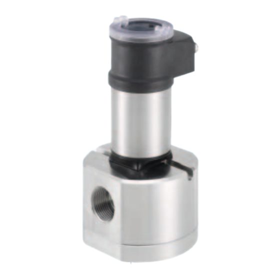
Burkert SE36 Quick Start Manual (126 pages)
Flowmeter and Flow transmitter
Brand: Burkert
|
Category: Measuring Instruments
|
Size: 5 MB
Table of Contents
Advertisement
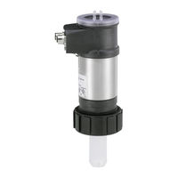
Burkert SE36 Operating Instructions Manual (74 pages)
Flowmeter and Flow transmitter
Brand: Burkert
|
Category: Measuring Instruments
|
Size: 5 MB
Table of Contents

Burkert SE36 Operating Instructions Manual (74 pages)
Flowmeter and Flow transmitter
Brand: Burkert
|
Category: Measuring Instruments
|
Size: 1 MB
Table of Contents
Advertisement

Burkert SE36 Quick Start Manual (42 pages)
Flowmeter and Flow transmitter
Brand: Burkert
|
Category: Transmitter
|
Size: 0 MB
Table of Contents

Burkert SE36 Quick Start Manual (44 pages)
Flowmeter and Flow transmitter
Brand: Burkert
|
Category: Measuring Instruments
|
Size: 2 MB
Table of Contents
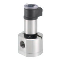
Burkert SE36 Manual (5 pages)
Positive displacement flowmeter
Brand: Burkert
|
Category: Measuring Instruments
|
Size: 1 MB