Sign In
Upload
Manuals
Brands
Branson Manuals
Controller
2000X Series
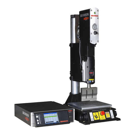
Branson 2000X Series Manuals
Manuals and User Guides for Branson 2000X Series. We have
4
Branson 2000X Series manuals available for free PDF download: Operation Manual, Instruction Manual
Branson 2000X Series Operation Manual (317 pages)
Brand:
Branson
| Category:
Power Supply
| Size: 3 MB
Table of Contents
Table of Contents
3
Safety and Support
9
Safety Requirements and Warnings
9
Symbols Found in this Manual
9
Chapter 1: Safety and Support General Precautions
10
Symbols Found on the Product
10
General Precautions
10
Intended Use of the System
11
Emissions
11
Setting up the Workplace
11
Chapter 1: Safety and Support How to Contact Branson
12
How to Contact Branson
12
The 2000X Energy Power Supply
13
Models Covered
13
Power Supply Manual and Guides
14
Actuator Manuals
14
Overview of These Models
14
Compatibility with Branson Products
15
Features
15
The Welding System
15
Chapter 2: The 2000X Energy Power Supply Features
16
The Power Supply
18
The Actuator
18
Module and Front Panel Controls
20
Welding Systems
21
Principle of Operation
21
Glossary of Terms
21
Chapter 2: The 2000X Energy Power Supply Glossary of Terms
22
Delivery and Handling
27
Shipping and Handling
27
Environmental Specifications
27
Chapter 3: Delivery and Handling Receiving
28
Receiving
28
Scope of Delivery
28
Unpacking
29
Chapter 3: Delivery and Handling Returning Equipment
30
Returning Equipment
30
Installation and Setup about Installation
32
About Installation
32
Handling and Unpacking
33
Unpack the Power Supply
34
Unpack the Stand or Actuator
34
Stand (Actuator on a Base)
34
Stand (Actuator on a Hub)
36
Actuator (Alone)
37
Chapter 4: Installation and Setup Take Inventory of Small Parts
38
Take Inventory of Small Parts
38
Cables
39
Chapter 4: Installation and Setup Installation Requirements
40
Installation Requirements
40
Location
40
Environmental Specifications
43
Electrical Input Power Ratings
43
Factory Air
44
Installation Steps
45
Mounting the Stand (Actuator on Base)
45
Mounting the Stand (Actuator on Hub-Mounted Column)
46
Actuator (Alone)
47
Mount the Power Supply
49
Interconnect between Power Supply and Actuator
50
Input Power (Main)
50
Output Power (RF Cable)
50
Interconnect between Power Supply and Actuator
52
Start Switch Connection (Automation)
54
Serial (RS-232) Port Connector
55
Parallel Printer Connector
55
User I/O Interface
57
Input Power Plug
60
User I/O DIP Switch (SW1)
62
Power Supply Module Options DIP Switch
62
Guards and Safety Equipment
65
Emergency Stop Control
65
Chapter 4: Installation and Setup Guards and Safety Equipment
66
Rack Mount Installation
67
Assemble the Acoustic Stack
68
For a 20Khz System
69
For a 30Khz System
69
For a 40Khz System
70
Assembling the Acoustic Stack
71
(Shown with Rectangular Horn Secured in the Vise.)
71
Connecting Tip to Horn
72
Installing the Ultrasonic Stack in the Actuator
72
15Khz, 20Khz, and 30Khz CA Converter Stacks
72
40 Khz Stacks
74
Mounting the Fixture on the Branson Base
75
(Hardware and Mounting Holes)
75
Testing the Installation
76
Still Need Help? or Parts? Have Questions
77
Chapter 4: Installation and Setup Still Need Help? or Parts? Have Questions
78
Technical Specifications Technical Specifications
79
Environmental Requirements
79
Technical Specifications
80
Electrical Requirements
80
Power Supply Rating
80
Pneumatic Requirements
81
Air Filter
81
Physical Description
81
Chapter 5: Technical Specifications Physical Description
82
Standard Modules and Components
83
Circuit Descriptions
83
Converters and Boosters
85
Customer-Provided Options
91
Technical Specifications
92
Operation
93
External Communication Options
94
Remote Networking
94
Ethernet
95
Front Panel Controls
95
Front Panel Keypad and Indicators
95
Chapter 6: Operation
95
Chapter 6: Operation Front Panel Controls
96
Testing the Welding System
98
System Menus
99
Using the Run Screen
99
Chapter 6: Operation System Menus
100
Chapter 6: Operation Setting Primary Parameters
104
Setting Primary Parameters
104
Using Time Weld Mode
106
Using Energy Weld Mode
110
Using Peak Power Weld Mode
114
Using Ground Detect Weld Mode
118
Setting Other Weld Parameters
122
Energy Brake
131
Digital UPS Setup
132
Setting the Timeout
138
Setting Limits
141
Saving and Recalling Presets
149
Saving a Preset
151
Recalling a Preset
154
Clearing a Preset
156
Preset Information
158
Chapter 6: Operation Printing
160
Printing
160
Setting up Your Printer
168
Using the Diagnostics Menu
171
Viewing Diagnostics
173
Viewing System Information
179
Viewing System Information
181
Using the System Configuration Menu
183
Setting a Password
189
Setting the System Time
198
Setting the System Date
199
Using the Horn down Feature
217
Using the Test Feature
218
2000 Series Preventive Maintenance
220
Periodically Clean the Equipment
220
Reconditioning the Stack (Converter, Booster, and Horn)
221
Routine Component Replacement
221
Chapter 7: Maintenance Parts Lists
222
Parts Lists
222
System Cables
223
Suggested Spares
224
Printer and Terminal Component Part Numbers
225
Circuits
225
Chapter 7: Maintenance Troubleshooting
228
Troubleshooting
228
System Alarm Tables
229
Alarm Index
229
Cycle Modified Alarms
230
Failure of Alarms and Messages
232
Alarm Condition
234
No Cycle Alarms and Messages
237
Suspect/Reject Alarms and Messages
239
Setup Alarms and Messages
245
Overload Alarms
261
Note Alarms
263
Service Events
265
Required Tools
265
Voltage Test Points
265
Chapter 7: Maintenance Service Events
266
Cold Start Procedures
266
Performing a Cold Start
267
Parts Replacement
269
Power Supply Cover
269
Chapter 7: Maintenance Parts Replacement
270
Circuit Boards and Modules
271
Power Switch and Lamp
272
Front Panel Membrane and VFD Display
272
Power Supply Module
273
DC Power Supply
274
User I/O Board
274
Battery for Backup RAM (BBRAM)
275
Power Supply Module
275
DC Power Supply
275
System Controller Board
276
Line Board
277
Line Fuses
278
Cooling Fans
279
Appendix A Remote Terminal
281
Setting up the Remote Terminal
282
Starting the Remote Terminal
282
Control by the Remote Terminal
282
Using the Remote Terminal
285
Remote Terminal Keyboard Equivalents
285
Viewing Weld Data
286
Switching Control Back to the Front Panel
287
Turning off the Remote Terminal
287
Appendix B Terminal Settings
289
Terminal Setup
289
Appendix C Compatible Printers
293
General
293
Printer Control
294
Emulation Mode
294
Appendix D Automation
297
Faq: 2000 Series Automation
297
Advertisement
Branson 2000X Series Operation Manual (180 pages)
Brand:
Branson
| Category:
Controller
| Size: 2 MB
Table of Contents
Table of Contents
3
Read this Chapter First
7
Read this Chapter First
8
Availability of this Operating Manual
8
Copyright
9
Product Liability, Intended Use, and Warranty
10
Warranty Terms
11
Requirements for Operating and Maintenance Personnel
12
Safety Instructions and Service
13
Safety and Warning Notes
14
Operating Personnel: Authorized Personnel
18
Sources of Danger Specific to Ultrasonic Technology
19
Intended Use of the Unit
22
Scope of Validity of the Operating Manual
22
Safety Features on the Unit
23
Safety Checks
24
Safety During Maintenance and Installation
25
Emissions
27
Workplace Setup
28
Manufacturer's Note on Electromagnetic Compatibility
29
Sales and Delivery Conditions
30
Introduction
31
Overview of the Actuators
32
Installation Options
42
Component Descriptions
45
Delivery and Handling
49
Transport and Handling
50
Delivery
51
Unpacking the Actuator
52
Installation and Setup
61
Installation Requirements
62
General Conditions for Connecting the Actuators to the Round and Square Column
76
Installation Steps
79
Protective and Safety Equipment
101
Stack Components
102
Assembling the Stack
104
Installing the Stack in the Actuator
108
Tool Change System (Not for the Micro Actuators)
111
Mounting the Weld Part Fixture on the BRANSON Base Plate
113
Checking the Installation
114
Do You Have Questions
114
Technical Specifications
115
Control Elements and Displays
119
Operating the Ao and Ae Actuators
121
Control Elements of the Ao and Ae Actuators
122
Basic Configuration of the Ao and Ae Actuators
123
Operating the Ao and Ae Actuators
123
Operating the Aod, Aed and Aodm Actuators
129
Control Elements of the Aod, Aed and Aodm Actuators
130
Basic Configuration of the Aod, Aed and Aodm Actuators
131
Operating the Aod, Aed and Aodm Actuators
131
Operating the Aef, Aemc and Aomc Actuators
137
Control Elements of the Aef, Aemc and Aomc Actuators
138
Basic Configuration of the Aef, Aemc and Aomc Actuators
139
Operating the Aef, Aemc and Aomc Actuators
139
Maintenance
147
Calibration
148
Maintenance
148
Parts Lists
155
Branson 2000X Series Instruction Manual (120 pages)
Brand:
Branson
| Category:
Controller
| Size: 2 MB
Table of Contents
Table of Contents
5
Chapter 1 : Safety and Support
14
Safety Requirements and Warnings
14
Symbols Found in this Manual
14
Symbols Found on the Product
14
General Precautions
16
Intended Use of the System
18
Safety Measures and Guards
18
Emissions
18
Setting up the Workplace
18
Regulatory Compliance
18
Warranty Statement, Disclaimer
19
How to Contact Branson
22
Before Calling Branson for Assistance
22
Returning Equipment for Repair
23
Get an RGA Number
24
Record Information about the Problem
24
Departments to Contact
25
Pack and Ship the Equipment
26
Obtaining Replacement Parts
26
Models Covered
30
Power Supply Manual Set
31
Chapter 2 Introduction to the 2000X Aed Actuator Models Covered
30
Overview of this Model
31
Features of the System
32
Controls and Indicators
34
Welding Systems
35
Glossary of Terms
37
Chapter 3 Delivery and Handling Shipping and Handling
43
Environmental Specifications
43
Receiving
44
Unpacking
45
Actuator Assemblies
45
Returning Equipment
45
Chapter 4 Installation and Setup about Installation
48
About Installation
48
Unpack the Power Supply
49
Unpack the Stand or Actuator
49
Stand (Actuator on a Base)
50
Stand (Actuator on a Hub)
52
Actuator (Alone)
53
Handling and Unpacking
48
Take Inventory of Small Parts
53
Cables
54
Installation Requirements
55
Location
55
Environmental Specifications
56
Electrical Input Power Ratings
56
Air Cylinder Consumption
57
Factory Air
62
Installation Steps
63
Mounting the Stand (Actuator on Base)
63
Mounting the Stand (Actuator on Hub-Mounted Column)
65
Actuator (Alone)
66
Mount the Power Supply
68
Input Power (Main)
69
Output Power (RF Cable)
69
Interconnect between Power Supply and Actuator
69
Start Switch Connection (Automation)
70
Serial (RS-232) Port Connector
71
Parallel Printer Connector, 2000X Time and 2000X Energy Only
71
User I/O Interface
72
Input Power Plug
75
User I/O DIP Switch (SW1)
76
Module Options DIP Switch
76
Guards and Safety Equipment
77
Emergency Stop Control
77
Rack Mount Installation
78
Assemble the Acoustic Stack
79
For a 15 Khz System
80
For a 20Khz System
80
For a 30Khz System
81
For a 40Khz System
81
Assembling the Acoustic Stack
82
Connecting Tip to Horn
83
Installing the Stack in the Actuator
84
Mounting the Fixture on the Branson Base
87
Testing the Installation
88
Still Need Help
89
Chapter 5: Technical Specifications Technical Specifications
91
Requirement Specifications
91
Performance Specifications
92
Physical Description
93
Standard Items
93
Chapter 6: Operation
97
Actuator Controls
97
Initial Actuator Settings
98
Regulated Air Pressure and Air Pressure Gauge
98
Factory Air Source
99
Downspeed Control
99
Actuator Alignment and Height (Horn Travel)
100
Mechanical Stop
100
Emergency Stop
101
Operating the Actuator
101
Calibration
103
Chapter 7 : Maintenance
103
Periodic and Preventive Maintenance
103
Periodically Clean the Equipment
103
Recondition the Stack (Converter, Booster, and Horn)
104
Routine Component Replacement
106
Parts Lists
107
Advertisement
Branson 2000X Series Instruction Manual (112 pages)
Brand:
Branson
| Category:
Controller
| Size: 0 MB
Table of Contents
Table of Contents
5
Chapter 1 : Safety and Support
14
Safety Requirements and Warnings
14
Symbols Found in this Manual
14
Symbols Found on the Product
14
General Precautions
15
Intended Use of the System
17
Safety Measures and Guards
18
Emissions
18
Setting up the Workplace
18
Regulatory Compliance
18
Warranty Statement, Disclaimer
18
How to Contact Branson
22
Before Calling Branson for Assistance
22
Returning Equipment for Repair
23
Get an RGA Number
24
Record Information about the Problem
24
Departments to Contact
25
Pack and Ship the Equipment
26
Obtaining Replacement Parts
26
Chapter 2 : Introduction to the 2000X Ao Actuator
28
Models Covered
28
Actuator Manual Set
29
Introduction to the 2000X Ao Actuator Models Covered
28
Power Supply Manual Set
28
Overview of this Model
29
Features of the System
30
Controls and Indicators
33
Welding Systems
34
Glossary of Terms
36
Delivery and Handling
41
Shipping and Handling
41
Environmental Specifications
41
Receiving
42
Unpacking
43
Actuator Assemblies
43
Returning Equipment
43
About Installation
46
Unpack the Stand or Actuator
47
Stand (Actuator on a Base)
47
Stand (Actuator on a Hub)
49
Actuator (Alone)
50
Chapter 4 : Installation and Setup
46
Installation and Setup about Installation
46
Handling and Unpacking
46
Take Inventory of Small Parts
51
Cables
52
Installation Requirements
53
Location
53
Environmental Specifications
53
Electrical Input Power Ratings
54
Air Cylinder Consumption
55
Factory Air
59
Installation Steps
60
Mounting the Stand (Actuator on Base)
60
Mounting the Stand (Actuator on Hub-Mounted Column)
61
Actuator (Alone)
62
Mount the Power Supply
64
Input Power (Main)
65
Output Power (RF Cable)
65
Interconnect between Power Supply and Actuator
65
Start Switch Connection (Automation)
67
Serial (RS-232) Port Connector
68
Parallel Printer Connector
68
User I/O Interface
68
Input Power Plug
71
User I/O DIP Switch (SW1)
72
Module Options DIP Switch
72
Rack Mount Installation
73
Guards and Safety Equipment
73
Emergency Stop Control
73
Assemble the Acoustic Stack
75
For a 20Khz System
75
For a 30Khz System
76
For a 40Khz System
76
Assembling the 20Khz Acoustic Stack
77
Connecting Tip to Horn
78
Installing the Stack in the Actuator
79
Mounting the Fixture on the Branson Base
81
Testing the Installation
82
Still Need Help
83
Technical Specifications
85
Requirement Specifications
85
Performance Specifications
86
Physical Description
87
Standard Items
87
Operation
91
Actuator Controls
91
Chapter 6 : Operation
92
Initial Actuator Settings
92
Regulated Air Pressure and Air Pressure Gauge
92
Factory Air Source
93
Downspeed Control
93
Dynamic Trigger
93
Actuator Alignment and Height (Horn Travel)
94
Mechanical Stop
94
Emergency Stop
95
Operating the Actuator
95
Maintenance
97
Calibration
97
Periodic and Preventive Maintenance
97
Periodically Clean the Equipment
97
Recondition the Stack (Converter, Booster, and Horn)
98
Routine Component Replacement
100
Parts Lists
101
Index
107
Advertisement
Related Products
Branson 2000X aed
Branson 2000X ao
Branson 20R series
Branson 2000 series
Branson 2000Xc
Branson 2000IW+
Branson 2100
Branson 2400
Branson 2510R-DTH
Branson 2800h
Branson Categories
Tractor
Power Supply
Ultrasonic Jewelry Cleaner
Laboratory Equipment
Controller
More Branson Manuals
Login
Sign In
OR
Sign in with Facebook
Sign in with Google
Upload manual
Upload from disk
Upload from URL