Sign In
Upload
Manuals
Brands
Branson Manuals
Controller
2000X aed
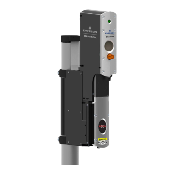
User Manuals: Branson 2000X aed Ultrasonic System
Manuals and User Guides for Branson 2000X aed Ultrasonic System. We have
2
Branson 2000X aed Ultrasonic System manuals available for free PDF download: Original Instructions Manual, Instruction Manual
Branson 2000X aed Original Instructions Manual (120 pages)
Brand:
Branson
| Category:
Controller
| Size: 3 MB
Table of Contents
Table of Contents
5
Chapter 1: Safety and Support
11
Safety Requirements and Warnings
12
Figure 1.1 Safety Label Shown on the Top of the 2000X Aed Actuator
13
Figure 1.2 Connector Label on the 2000X Aed Actuator
13
Figure 1.3 Caution Label on the 2000X Aed Actuator for the Factory Air Supply
13
Figure 1.4 Safety Labels on Front of the 2000X Aed Actuator
14
General Precautions
15
Table 1.1 Manufacturers of Protective Materials and Equipment
16
Figure 1.5 CE Mark
18
Warranty
19
How to Contact Branson
20
Returning Equipment for Repair
21
Table 1.2 Branson Contacts
22
Obtaining Replacement Parts
24
Disposing Obsolete Machines and Accessories
25
Chapter 2: Introduction to the 2000X Aed Actuator
27
Models Covered
28
Figure 2.1 Left Side View of the 2000X Aed Actuator
28
Figure 2.2 Left Side View of the 2000X Aed 15 Khz Actuator
29
Overview of this Model
30
Features of the System
31
Controls and Indicators
32
Welding Systems
33
Glossary
35
Chapter 3: Delivery and Handling
39
Shipping and Handling
40
Table 3.1 Environmental Specifications
40
Receiving
41
Table 3.2 Inspect the Actuator When It Is Delivered
41
Unpacking
42
Returning Equipment
43
Chapter 4: Installation and Setup
45
About Installation
46
Handling and Unpacking
47
Figure 4.1 Linear Encoder Is Sensitive; Do Not Handle It
47
Figure 4.2 Unpacking the Stand (Actuator on a Base); Left-Side View of Stand
48
Figure 4.3 Unpacking the Stand (Actuator on a Base) and Left-Side View of Stand of the 2000X Aed 15 Khz Actuator
49
Figure 4.4 Unpacking the Stand (Actuator on a Hub); Hub Shown Separately
50
Figure 4.5 Ultrasonic Converter (J-Type for Stand-Alone Use) and Booster
51
Take Inventory of Small Parts
52
Table 4.1 Small Parts Included (=X) with Power Supply And/Or Actuator Assemblies
52
Table 4.2 List of Cables
53
Installation Requirements
54
Figure 4.6 Power Supply Dimensional Drawing
54
Figure 4.7 2000X Actuator Dimensional Drawing
54
Figure 4.8 2000X Aed 15 Khz Actuator Dimensional Drawing
54
Table 4.3 Environmental Specifications
54
Table 4.4 Input Power Requirements
55
Table 4.5 Cubic Feet of Air Per Minute Per Inch of Stroke Length (each Direction)
56
Figure 4.9 Block Wiring Diagram
60
Installation Steps
62
Figure 4.10 Base Mounting Centers
63
Figure 4.11 Base Mounting Centers Dimensional Drawing for 2000X Aed 15 Khz Actuator
63
Figure 4.12 Mounting Bolt Pattern for the Hub (for Stand on Hub)
64
Figure 4.13 Rear View of Actuator, Showing Mounting Surface, Bolt and Guide Pin Locations
66
Figure 4.14 Rear View of Actuator, Showing Mounting Surface, Bolt and Guide Pin Locations for 2000X Aed 15 Khz Actuator
67
Figure 4.15 Connections on Rear of Power Supply
68
Figure 4.16 Electrical Connections from Power Supply to a 2000X-Series Actuator
70
Figure 4.17 Start Switch Connection Codes
70
Table 4.6 Printer Compatibility
72
Figure 4.18 User I/O Cable Identification and Wire Color Diagram
73
Table 4.7 User I/O Cable Pin Assignments
73
Figure 4.19 Line Cord Color Code
75
Table 4.8 User I/O Input and Output Function Selection
75
Table 4.9 User I/O DIP Switch Functions
76
Guards and Safety Equipment
77
Figure 4.20 Actuator Emergency Stop Button
77
Rack Mount Installation
78
Figure 4.21 Detail of Rack Mount Handle Kit Assembly
78
Table 4.10 Rack Mount Handle Kit Assembly
78
Assemble the Acoustic Stack
80
Table 4.11 Tools
80
Table 4.12 Assemble the Acoustic Stack (for a 15 Khz System)
80
Table 4.13 Assemble the Acoustic Stack (for a 20 Khz System)
81
Table 4.14 Assemble the Acoustic Stack (for a 30 Khz System)
81
Table 4.15 Assemble the Acoustic Stack (for a 40 Khz System)
82
Figure 4.22 Assembling the 20 Khz Acoustic Stack
83
Table 4.16 Stud Torque Values
83
Figure 4.23 Connecting Tip to Horn
84
Table 4.17 Tip to Horn Torque Specifications
84
Figure 4.24 Installing a 20 Khz Stack in a Branson Actuator
85
Figure 4.25 Installing a 15 Khz Stack in a Branson Actuator
85
Figure 4.26 Installing a 40 Khz Stack in a Branson Actuator
86
Mounting the Fixture on the Branson Base (Hardware and Mounting Holes)77
87
Figure 4.27 Mounting Circles on Base
87
Testing the Installation
88
Figure 4.28 Normal Front Panel Display after Power-Up
88
Still Need Help
89
Chapter 5: Technical Specifications
91
Technical Specifications
92
Table 5.1 Environmental Specifications
92
Table 5.2 Max. Welding Force, Dynamic Trigger Force, Dynamic Follow-Through
92
Table 5.3 Maximum Traverse Speed (Application Dependant)
92
Physical Description
93
Table 5.4 Description of Controls on Base
93
Figure 5.1 2000X Actuator Pneumatic System
94
Chapter 6: Operation
97
Actuator Controls
98
Initial Actuator Settings
99
Table 6.1 to Adjust the Mechanical Stop
101
Operating the Actuator
102
Table 6.2 to Operate the 2000X Aed Actuator
102
Chapter 7: Maintenance
103
Calibration
104
Periodic and Preventive Maintenance
105
Table 7.1 Component Replacements Based on Cycles Run
107
Table 7.2 Accessories List for 2000X Aed Actuator
108
Table 7.3 Spare Parts List for the Actuator
110
Table 7.4 Accessories List for 2000X Aed 15 Khz Actuator
111
Table 7.5 Spare Parts List for the 2000X Aed 15 Khz Actuator
112
Table 7.6 Suggested Spares
113
Table A.1 Manual Revisions
116
Advertisement
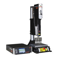
Branson 2000X aed Instruction Manual (120 pages)
Brand:
Branson
| Category:
Controller
| Size: 2 MB
Table of Contents
Table of Contents
5
Chapter 1 : Safety and Support
14
Safety Requirements and Warnings
14
Symbols Found in this Manual
14
Symbols Found on the Product
14
General Precautions
16
Intended Use of the System
18
Safety Measures and Guards
18
Emissions
18
Setting up the Workplace
18
Regulatory Compliance
18
Warranty Statement, Disclaimer
19
How to Contact Branson
22
Before Calling Branson for Assistance
22
Returning Equipment for Repair
23
Get an RGA Number
24
Record Information about the Problem
24
Departments to Contact
25
Pack and Ship the Equipment
26
Obtaining Replacement Parts
26
Models Covered
30
Power Supply Manual Set
31
Chapter 2 Introduction to the 2000X Aed Actuator Models Covered
30
Overview of this Model
31
Features of the System
32
Controls and Indicators
34
Welding Systems
35
Glossary of Terms
37
Chapter 3 Delivery and Handling Shipping and Handling
43
Environmental Specifications
43
Receiving
44
Unpacking
45
Actuator Assemblies
45
Returning Equipment
45
Chapter 4 Installation and Setup about Installation
48
About Installation
48
Unpack the Power Supply
49
Unpack the Stand or Actuator
49
Stand (Actuator on a Base)
50
Stand (Actuator on a Hub)
52
Actuator (Alone)
53
Handling and Unpacking
48
Take Inventory of Small Parts
53
Cables
54
Installation Requirements
55
Location
55
Environmental Specifications
56
Electrical Input Power Ratings
56
Air Cylinder Consumption
57
Factory Air
62
Installation Steps
63
Mounting the Stand (Actuator on Base)
63
Mounting the Stand (Actuator on Hub-Mounted Column)
65
Actuator (Alone)
66
Mount the Power Supply
68
Input Power (Main)
69
Output Power (RF Cable)
69
Interconnect between Power Supply and Actuator
69
Start Switch Connection (Automation)
70
Serial (RS-232) Port Connector
71
Parallel Printer Connector, 2000X Time and 2000X Energy Only
71
User I/O Interface
72
Input Power Plug
75
User I/O DIP Switch (SW1)
76
Module Options DIP Switch
76
Guards and Safety Equipment
77
Emergency Stop Control
77
Rack Mount Installation
78
Assemble the Acoustic Stack
79
For a 15 Khz System
80
For a 20Khz System
80
For a 30Khz System
81
For a 40Khz System
81
Assembling the Acoustic Stack
82
Connecting Tip to Horn
83
Installing the Stack in the Actuator
84
Mounting the Fixture on the Branson Base
87
Testing the Installation
88
Still Need Help
89
Chapter 5: Technical Specifications Technical Specifications
91
Requirement Specifications
91
Performance Specifications
92
Physical Description
93
Standard Items
93
Chapter 6: Operation
97
Actuator Controls
97
Initial Actuator Settings
98
Regulated Air Pressure and Air Pressure Gauge
98
Factory Air Source
99
Downspeed Control
99
Actuator Alignment and Height (Horn Travel)
100
Mechanical Stop
100
Emergency Stop
101
Operating the Actuator
101
Calibration
103
Chapter 7 : Maintenance
103
Periodic and Preventive Maintenance
103
Periodically Clean the Equipment
103
Recondition the Stack (Converter, Booster, and Horn)
104
Routine Component Replacement
106
Parts Lists
107
Advertisement
Related Products
Branson 2000X Series
Branson 2000X ao
Branson 2000 series
Branson 2000Xc
Branson 2000IW+
Branson 20R series
Branson 2800
Branson 2510
Branson Sonifier 250
Branson 2400h
Branson Categories
Tractor
Power Supply
Ultrasonic Jewelry Cleaner
Laboratory Equipment
Controller
More Branson Manuals
Login
Sign In
OR
Sign in with Facebook
Sign in with Google
Upload manual
Upload from disk
Upload from URL