Branson 2000X Series Instruction Manual
Hide thumbs
Also See for 2000X Series:
- Instruction manual (120 pages) ,
- Operation manual (180 pages) ,
- Operation manual (317 pages)

Related Manuals for Branson 2000X Series


Summary of Contents for Branson 2000X Series
- Page 1 2000X ao Actuator Instruction Manual EDP 100-214-281 Rev. 07 Software Version 10.xx and above BRANSON Ultrasonics Corporation 41 Eagle Road Danbury, Connecticut 06813-1961 U.S.A. (203) 796-0400...
- Page 3 2000X ao Actuator Manual Change Information At Branson, we strive to maintain our position as the leader in ultrasonics plas- tics joining, cleaning and related technologies by continually improving our cir- cuits and components in our equipment. These improvements are incorporated as soon as they are developed and thoroughly tested.
- Page 4 Foreword Congratulations on your choice of a Branson Ultrasonics Corporation system! The Branson 2000X-Series system is process equipment for the joining of plastic parts using ultrasonic energy. It is the newest generation of product using this sophisticated technology for a variety of customer applications. This Instruction Manual is part of the documentation set for this system, and should be kept with the equipment.
-
Page 5: Table Of Contents
Warranty Statement, Disclaimer - - - - - - - - - - - - - - - 1-6 How to Contact Branson - - - - - - - - - - - - - - - - - - -1-10 1.4.1... - Page 6 3.1.1 Environmental Specifications - - - - - - - - - - - - - - - - 3-1 Receiving - - - - - - - - - - - - - - - - - - - - - - - - - - - 3-2 Unpacking - - - - - - - - - - - - - - - - - - - - - - - - - - 3-3 3.3.1 Actuator Assemblies - - - - - - - - - - - - - - - - - - - - 3-3...
- Page 7 Installing the Stack in the Actuator - - - - - - - - - - - - - 4-35 Mounting the Fixture on the Branson Base- - - - - - - - - -4-37 4.10 Testing the Installation - - - - - - - - - - - - - - - - - - - -4-38 4.11 Still Need Help? - - - - - - - - - - - - - - - - - - - - - - - -4-39...
- Page 8 100-214-281 Rev. 07...
- Page 9 Connecting Tip to Horn - - - - - - - - - - - - - - - - - - - - - - - - - - - 4-34 fig. 4.19 Installing a 20kHz Stack in a Branson Actuator - - - - - - - - - - - - - - - - 4-35 fig. 4.20 Installing a 40kHz Stack in a Branson Actuator - - - - - - - - - - - - - - - - 4-36 fig.
- Page 10 100-214-281 Rev. 07...
- Page 11 Warranty Period - - - - - - - - - - - - - - - - - - - - - - - - - - - - 1-8 tab. 1.2 Branson Contacts - - - - - - - - - - - - - - - - - - - - - - - - - - 1-13 tab. 3.1 Environmental Specifications - - - - - - - - - - - - - - - - - - - - - 3-1 tab.
- Page 12 viii 100-214-281 Rev. 07...
- Page 13 Warranty Statement, Disclaimer - - - - - - - - - - - - - - - 1-7 How to Contact Branson - - - - - - - - - - - - - - - - - - 1-10 1.4.1...
-
Page 14: Safety Requirements And Warnings
Chapter 1: Safety and Support Safety Requirements and Warnings 1.1 Safety Requirements and Warnings 1.1.1 Symbols Found in this Manual Three symbols used throughout this manual warrant special attention: NOTE A Note contains important information. It does not alert the user to potential injury, but only to a situation that might eventually require additional work or modification if you ignore it initially. -
Page 15: General Precautions
2000X ao Actuator Chapter 1: Safety and Support Instruction Manual General Precautions Figure 1.2 Caution label on the aod Actuator for the factory air supply Figure 1.3 Safety Labels on front of the aod Actuator 1.2 General Precautions Take the following precautions before servicing the power supply: •... - Page 16 Chapter 1: Safety and Support General Precautions circuit reference, not chassis ground. Therefore, use only non-grounded, battery-powered multimeters when testing these modules. Using other types of test equipment can present a shock hazard. • Be sure power is disconnected from the power supply before setting a DIP switch. •...
-
Page 17: Intended Use Of The System
2000X ao Actuator Chapter 1: Safety and Support Instruction Manual General Precautions Softcomm Products Elvex Corp 2310 - T South Airport Blvd. 13 Trowbridge Drive Chandler, AZ 85224 Bethel, CT 06801 Sound Absorbing Material American Acoustical Products Tamer Industries 6 October Hill Road 185 Riverside Av. -
Page 18: Safety Measures And Guards
The following excerpts from the “Terms and Conditions of Sale” (found on the back of your Invoice) are essential guidelines for the product Warranty issued with your Branson ultrasonic welding components. The items listed in this section specifically address issues involving the delivery, shipment, and warranty period provided. - Page 19 Warranty Statement, Disclaimer TERMS AND CONDITIONS OF SALE Branson Ultrasonics Corporation is herein referred to as the “Seller” and the customer or person or entity purchasing products (“Products”) from Seller is referred to as the “Buyer.” Buyer’s acceptance of the Products will manifest Buyer’s assent to these Terms and Conditions.
- Page 20 Warranty Statement, Disclaimer ULTRASONIC JOINING EQUIPMENT NORTH AMERICAN WARRANTY POLICY Each product manufactured by Branson is guaranteed to be free from defects in material and workmanship for a period of time specified in Table 1 .1 Warranty Period from the date of invoice.
- Page 21 Repair service at the customer site • Includes parts and labor at the customer site performed by a Branson technician. The cus- tomer is responsible for all travel-related charges.
-
Page 22: How To Contact Branson
How to Contact Branson 1.4 How to Contact Branson Branson is here to help you. We appreciate your business and are interested in helping you suc- cessfully use our products. To contact Branson for help, use the following telephone numbers, or contact the field office nearest you. -
Page 23: Returning Equipment For Repair
Branson representative, or the shipment may be delayed or refused If you are returning equipment to Branson for repair, you must first call the Repair department to obtain a Returned Goods Authorization (RGA) number. (If you request it, the repair depart- ment will fax a Returned Goods Authorization form to fill out and return with your equipment.) -
Page 24: Get An Rga Number
1.5.1 Get an RGA Number RGA# _____________ If you are returning equipment to Branson, please call the Repair Department to obtain a Returned Goods Authorization (RGA) number. (At your request, the Repair Department will fax an RGA form to fill out and return with the equipment.) 1.5.2 Record information about the Problem... -
Page 25: Departments To Contact
Chapter 1: Safety and Support Instruction Manual Returning Equipment for Repair 1.5.3 Departments to Contact Call your local Branson Representative, or contact Branson by calling, and asking for the appro- priate department as indicated in Table 1.2: Branson Contacts below. -
Page 26: Pack And Ship The Equipment
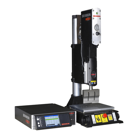
_______________________________________________________________________ _______________________________________________________________________ _______________________________________________________________________ 1.6 Obtaining Replacement Parts You can reach Branson Parts Store at the following telephone numbers: Branson Part Store direct telephone number: 877-330-0406 fax number: 877-330-0404 Many parts can be shipped the same day if ordered before 2:30 p.m., Eastern time. - Page 27 Figure 2-1 shows a Branson 2000X ao Actuator mounted on a column support which, in turn is mounted on a column, and is supported by the ergonomic base.
-
Page 28: Introduction To The 2000X Ao Actuator Models Covered
Stop Adjust Base 2.1.1 Power Supply Manual Set The following documentation is available for the Branson 2000X-series Power Supplies that are compatible with the 2000X ao Actuator: • 2000X ea Power Supply Instruction Manual (EDP 100-214-278) • 2000-Series Installation Guide (EDP 100-214-226) •... -
Page 29: Actuator Manual Set
2000X ao is controlled by inputs to the 2000X ea Power Supply. Having remote pneumatic controls allows easier user access to the Actuator settings, often important in automated systems. The pneumatics covered in this manual refer to the remote box package sold by Branson. Some customers may require custom controls. -
Page 30: Features Of The System
2.3 Features of the System Listed below are many features of the Branson 2000X-series ultrasonic welding system included in a ao2000X ao Actuator and 2000X Series Power Supply. •... - Page 31 • Amplitude Stepping: A patented Branson process, controlled by the Power Supply. At a specified time, energy, peak power, distance, or by external signal you can change the amplitude during the weld to control the flow of plastic. This feature helps ensure part consistency, higher strength parts and control of flash.
- Page 32 System Information Screen: This is a screen that will give you information about your welding system (e.g., cylinder size, stroke length, number of cycles). Refer to this screen when contacting Branson for service and support. • Feature Advanced or Normal: To simplify the menus the 2000a Power Supply can be set to Normal.
-
Page 33: Controls And Indicators
2000X ao Actuator Chapter 2: Introduction to the 2000X ao Actuator Instruction Manual Controls and Indicators 2.4 Controls and Indicators The Actuator Controls for the 2000X ao Actuator are found in two locations: on the Actuator or on the Remote Pneumatics Box. The 2000X rp is a separate component of a 2000X ao. System controls and Actuator power are provided by the 2000X-series Power Supply. -
Page 34: Welding Systems
Actuator and related welding, tooling, and parts-handling systems. The 2000X Series Power Supply also contains a DC power supply for electrical power to operate the electrical components and control circuits in the power supply, and on the Actuator. - Page 35 2000X ao Actuator Chapter 2: Introduction to the 2000X ao Actuator Instruction Manual Welding Systems Boosters are designed to resonate at the same frequency as the converter with which they are used. Boosters are usually mounted at a nodal (minimum vibration) point of axial motion. This minimizes the loss of energy and prevents vibration from being transmitted into the actuator.
-
Page 36: Glossary Of Terms
Baud Rate: The rate of data transmission over the serial communication port. Beep: An audible signal produced by the Branson control board. Used to alert the operator to an unexpected condition. Calibrate Actuator: The menus that guide you through the actuator calibration to calibrate dis- tance and force that must compensate for horn mass and return spring force. - Page 37 2000X ao Actuator Chapter 2: Introduction to the 2000X ao Actuator Instruction Manual Glossary of Terms Calibrate Sensors: The ability to calibrate the reported pressure sensor and force against an out- side standard. Calibrate Standards: The menu title for accessing the calibration and verification of pressure, force, power, and energy.
- Page 38 Chapter 2: Introduction to the 2000X ao Actuator Glossary of Terms General Alarm: An alarm that occurs due to system fault and/or tripping a limit. Ground Det. Cutoff: Ground Detect Cutoff. Immediately terminates the weld process, includ- ing the hold step, when a ground detect has occurred. Gnd Det.
- Page 39 2000X ao Actuator Chapter 2: Introduction to the 2000X ao Actuator Instruction Manual Glossary of Terms Post Weld Seek: Used to determine the operating frequency of the Stack, after the Hold and/or Afterburst portion of the weld cycle. Ultrasonics are run at a low level (5%) amplitude during this step, and the frequency is stored to memory.
- Page 40 Chapter 2: Introduction to the 2000X ao Actuator Glossary of Terms Step @ Ext Sig: Allows you to shift either force or amplitude based upon an external signal. Step @ Force: User-definable point at which AmpA is changed to AmpB. Step @ Power: User-definable point at which AmpA or ForceA is changed to AmpBor ForceB.
-
Page 41: Delivery And Handling
2000X ao Actuator Chapter 3: Delivery and Handling Instruction Manual Shipping and Handling Chapter 3: Delivery and Handling Shipping and Handling - - - - - - - - - - - - - - - - - - - - 3-1 3.1.1 Environmental Specifications - - - - - - - - - - - - - - - - 3-1 Receiving - - - - - - - - - - - - - - - - - - - - - - - - - - - 3-2... -
Page 42: Receiving
Chapter 3: Delivery and Handling Receiving 3.2 Receiving Branson Actuator units are carefully checked and packed before dispatch. It is recommended, however, that you follow the procedure below upon receiving your Actuator. Inspect the Actuator when it is delivered: Step:... -
Page 43: Unpacking
3.4 Returning Equipment If you are returning equipment to Branson Ultrasonic Corporation, please call your Customer Service Representative to receive approval to return goods to Branson. If you are returning equipment for repair refer to... - Page 44 Chapter 3: Delivery and Handling Returning Equipment 100-214-281 Rev. 07...
- Page 45 2000X ao Actuator Chapter 4: Installation and Setup Instruction Manual Chapter 4: Installation and Setup About Installation - - - - - - - - - - - - - - - - - - - - - - - 4-2 Handling and Unpacking - - - - - - - - - - - - - - - - - - - 4-2 4.2.1 Unpack the Stand or Actuator - - - - - - - - - - - - - - - 4-3...
-
Page 46: Installation And Setup About Installation
Installing the Stack in the Actuator- - - - - - - - - - - - - 4-35 Mounting the Fixture on the Branson Base - - - - - - - - - 4-37 4.10 Testing the Installation - - - - - - - - - - - - - - - - - - - 4-38 4.11 Still Need Help? - - - - - - - - - - - - - - - - - - - - - - - 4-39... -
Page 47: Unpack The Stand Or Actuator
• Actuators (alone) are shipped in a rigid cardboard box using protective foam shells for sup- port. Depending on which one of the following options applies to you, unpack the Branson actuator assembly: 4.2.2 Stand (actuator on a base) CAUTION Heed the “This End Up”... - Page 48 Chapter 4: Installation and Setup Handling and Unpacking Move the shipping container close to the intended installation location, leave it on the floor. Open the top of the box. Remove the insert from the top of the protective box, which may contain the booster, converter, and the toolkit.
-
Page 49: Stand (Actuator On A Hub)
2000X ao Actuator Chapter 4: Installation and Setup Instruction Manual Handling and Unpacking 4.2.3 Stand (Actuator on a Hub) Figure 4.2 Unpacking the Stand (Actuator on a Hub); Hub Shown Separately Booster Converter Note: Hubs may be lag-bolted to the Tool Kit Insert Box pallet for shipping purposes. -
Page 50: Actuator (Alone)
Chapter 4: Installation and Setup Handling and Unpacking Remove the block(s) of wood between the base and the support by slowly loosening the two column clamps (allowing the stand to rise slightly) and then cutting the shipping tape on the block of wood. RETIGHTEN THE COLUMN CLAMPS. -
Page 51: Take Inventory Of Small Parts
2000X ao Actuator Chapter 4: Installation and Setup Instruction Manual Take Inventory of Small Parts 4.3 Take Inventory of Small Parts Table 4.1 Small Parts included (=x) with Power Supply and/or Actuator Assemblies 2000X Power Supply Actuator Part or Kit 20kHz 30kHz 40kHz Stand (Base) Stand (Hub) (alone) T-Handle Wrench... -
Page 52: Cables
Chapter 4: Installation and Setup Take Inventory of Small Parts 4.3.1 Cables Two cables connect the power supply and actuator: the actuator interface cable, and the RF cable. If the sys- tem is to be automated, you may also need a J911 start cable and a user I/O cable. Check your invoice for cable types and cable lengths. -
Page 53: Installation Requirements
2000X ao Actuator Chapter 4: Installation and Setup Instruction Manual Installation Requirements 4.4 Installation Requirements 4.4.1 Location The actuator or stand may be installed in a variety of positions. The stand (on a base) is often manually oper- ated, using its base-mounted start switches, and so is installed at a safe and comfortable workbench height (approximately 30-36 inches) with the operator sitting or standing in front of the system. -
Page 54: Electrical Input Power Ratings
Chapter 4: Installation and Setup Installation Requirements 4.4.3 Electrical Input Power Ratings Plug the Power Supply into a single-phase, grounded, 3-wire, 50 or 60 Hz power source. Table 4.2 lists the current and fuse ratings for the various models. The ground screw on the rear of the actuator must be connected to earth ground with #8 gauge wire. Table 4.4 Input Power requirements 1250 W 200V - 240V... -
Page 55: Air Cylinder Consumption
2000X ao Actuator Chapter 4: Installation and Setup Instruction Manual Installation Requirements 4.4.4 Air Cylinder Consumption Cubic Feet of air per minute per inch of stroke length (each direction) Pressure 1.5" 0.00174 0.00243 0.00312 0.00381 0.00450 0.00513 0.00590 0.00660 0.00730 0.00800 2"... - Page 56 Chapter 4: Installation and Setup Installation Requirements Figure 4.4 Power Supply Dimensional Drawing 5.0” (127mm) Desired Clearance Air Intake 20.6” 522.9mm Air outlet is under 1.7” front panel 43.6mm 0.45” 13.4” 11.4mm 340.1mm 17.55” 445.8mm 5.2” 5.7” 132.4mm 144.8mm 4-12 100-214-281 Rev.
- Page 57 2000X ao Actuator Chapter 4: Installation and Setup Instruction Manual Installation Requirements Figure 4.5 ao Actuator Dimensional Drawing 43.0 1092mm machined mounting surfaces (3 places)** **These three mounting surfaces are flat within 0.004 in. (0.1mm) TIR, in a tolerance zone of 16 x 3.5 in. (410 x 90 mm). The surface to which the actuator is mounted must also have the same flatness tolerance.
- Page 58 Chapter 4: Installation and Setup Installation Requirements Figure 4.6 Block Wiring Diagram ACTUATOR REAR PANEL P73 J73 RF OU T RF RTN J75-B EXTLSSRC EXT MPS/GDS 24VRTN (OPTIONAL) EXTLSSIG J62-B CONVERTER SV1 PRIMARY SV1SRC (AE ONLY) SV1RTN +24VSRC SV2 DUAL FLOW SV2SRC (AE ONLY) SV2RTN...
-
Page 59: Factory Air
Failure to connect cooling air may void product warranty. Consult with a Branson representative if you have any questions. You must provide an air filter assembly to the remote box which will support at least 100 psig and remove particulate matter of 5 microns or larger. -
Page 60: Installation Steps
Chapter 4: Installation and Setup Installation Steps 4.5 Installation Steps WARNING This product is heavy and can cause a pinching or crushing injury during installation or adjustment. Keep clear of moving parts and do not loosen clamps unless directed to do so. CAUTION If a stand is not mounted in a vertical position, the air filter (on the column support) must be removed, reoriented, and replumbed. -
Page 61: Mounting The Stand (Actuator On Hub-Mounted Column)
2000X ao Actuator Chapter 4: Installation and Setup Instruction Manual Installation Steps Figure 4.7 Base Mounting Centers 28.0 in / 711 mm 7.37 in / 187 mm 16.5 i 75 in / 5 mm 419 m Mounting Holes accept 3/8 inch or metric M10 cap screws 21.31 in / 541 mm... -
Page 62: Actuator (Alone)
Chapter 4: Installation and Setup Installation Steps Figure 4.8 Mounting Bolt Pattern for the Hub (for Stand on Hub) 10.50 in / 267 mm Front of Hub 3/8 inch or 6.00 in / 152 mm M10 bolts (4 places) 3.94 in / 100mm 5.25 in / 133 mm 0.59 in / 0.94 in / 24 mm... - Page 63 2000X ao Actuator Chapter 4: Installation and Setup Instruction Manual Installation Steps Lift the actuator from the box. Carefully lay the assembly on its right side (NOT on the side with the linear encoder). Use of a guide pin is suggested. It is not provided with the actuator. If you require a guide pin, use a solid metal dowel pin, 12mm diameter, which must not extend into the actuator more than 0.40 inch (10mm) from your support.
-
Page 64: Mount The Power Supply
The cable lengths are limited based on the operating frequency of the welding system. Performance and results can suffer if the RF cable is crushed, pinched, damaged or modified. Contact your Branson Repre- sentative if you have special cable requirements. In some cases, remote operation from a User I/O or a Host Computer can be used to solve a distance limitation. -
Page 65: Input Power (Main)
RF Cable and the Actuator Interface cable. A 37-pin cable is used for Power and Control Signalling between the Power Supply and a Branson Actuator. The cable connects to the rear of the Power Supply and the rear of the Actuator. - Page 66 MOD EL: AEP 4 30 Made in U.S .A. 1 01-1 34-106 Y EAR OF MAN UF A CTU RE 1 99 6 AOP/AO RE MOTE BRANSON ULTRASONICS CORPORATION Earth Ground 41 EAGLE RD., DANBURY, CT. 06813-1961 MODEL: AEP 430 Made in U.S.A.
-
Page 67: Start Switch Connection (Automation)
Installation Steps 4.5.8 Start Switch Connection (Automation) A Branson actuator requires two start switches and emergency stop connection. Stands on a base include this connection (factory installed and connected from the base) while the stand on a hub and actuator (alone) applications require the user make their own start switch/E-stop connections, as follows: Figure 4.12 Start Switch Connection Codes... -
Page 68: Serial (Rs-232) Port Connector
The Printer Connector can support one printer model, to provide printed reports of your weld information, and to provide graphical representation of your weld results. The printer interface is for a dot-matrix printer, using a 9-pin printing head. One printer model is available from Branson at the present time. 4.5.11 User I/O Interface The user I/O is a standard interface for automation, provided on the power supply. - Page 69 2000X ao Actuator Chapter 4: Installation and Setup Instruction Manual Installation Steps Table 4.5 User I/O Cable Pin Assignments. Signal Name Signal Type Direction Signal Range Definition Colors ACT_CLEAR 0V True Output 0/24V, 100mA Actuator clear signal Red/Wht AMPLITUDE_OUT Analog Output 0V to 10V Amplitude signal from PS...
- Page 70 Ensure all unused wires are properly isolated. failure to do so may result in Power Supply or system failure. NOTE Refer to the Branson Automation Guide (EDP 100-214-273) for additional infor- mation about selection and use of Input and Output features listed in the following Table.
-
Page 71: Input Power Plug
2000X ao Actuator Chapter 4: Installation and Setup Instruction Manual Installation Steps Table 4.6 User I/O Input and Output Function Selection Input Output J3_1_INPUT J3_8_OUTPUT Disabled Disabled J3_17_INPUT J3_22_OUTPUT Ext U/S Delay Confirm Preset Display Lock J3_19_INPUT J3_36_OUTPUT Ext Beeper Ext Cycle Abort J3_31_INPUT Cycle Okay... -
Page 72: User I/O Dip Switch (Sw1)
Chapter 4: Installation and Setup Installation Steps 4.5.13 User I/O DIP Switch (SW1) DIP switch SW1 for the user I/O is located next to the J3 on the back of the 2000X-series power supply. The settings of these switches affect the user I/O signals. Factory default setting is with all dip switches set to ON (switch position closest to number designation). -
Page 73: Guards And Safety Equipment
2000X ao Actuator Chapter 4: Installation and Setup Instruction Manual Guards and Safety Equipment 4.6 Guards and Safety Equipment 4.6.1 Emergency Stop Control If you use the Emergency Stop button on the Actuator to terminate a weld, twist the button to reset it. - Page 74 Chapter 4: Installation and Setup Rack Mount Installation NOTE Do not permanently remove the Cover from the Power Supply because it is required for proper system cooling. Step Procedure Order and obtain the Rack Mount kit for your Power Supply. The brackets in the Kit are designed for standard 19-inch rack mounting options.
-
Page 75: Assemble The Acoustic Stack
2000X ao Actuator Chapter 4: Installation and Setup Instruction Manual Assemble the Acoustic Stack 4.8 Assemble the Acoustic Stack CAUTION The following procedure must be performed by a setup person. If necessary, secure the larg- est portion of a square or rectangular horn in a soft jawed (brass or aluminum) vise. NEVER attempt to assemble or remove a horn by holding the converter housing or the booster clamp ring in a vise. -
Page 76: For A 30Khz System
Chapter 4: Installation and Setup Assemble the Acoustic Stack 4.8.2 For a 30kHz System Step Action Clean the mating surfaces of the converter, booster, and horn. Remove any foreign material from the threaded holes. Apply a drop of Loctite® 290 threadlocker (or equivalent) to the studs for the booster and horn Install the threaded stud into the top of the booster;... -
Page 77: Assembling The 20Khz Acoustic Stack
Vise Jaw protectors (aluminum or soft metal) Horn Vise Stack Assembly Torque Table NOTE The use of a Branson torque wrench or the equivalent is recommended. P/N 101- 063-617 for 20kHz systems and 101-063-618 for 40kHz systems. 100-214-281 Rev. 07 4-33... -
Page 78: Connecting Tip To Horn
Chapter 4: Installation and Setup Assemble the Acoustic Stack Table 4.9 Stud Torque Values Used On Stud Size Torque EDP # 20 kHz 1/2” x 20 x 1-1/4” 450 in.-lbs, 50.84 Nm. 100-098-370 20 kHz 1/2” x 20 x 1-1/2” 450 in.-lbs, 50.84 Nm. -
Page 79: Installing The Stack In The Actuator
5. Reinstall the door assembly, and start the four door screws. 6. Align the horn by rotating it, if necessary. Torque the carriage door to 20 in.-lbs to secure the stack. Figure 4.19 Installing a 20kHz Stack in a Branson Actuator Hex Screw... - Page 80 Make sure that the system power is turned off by disconnecting the power plug. Place the converter / booster in the sleeve. Loosen the four carriage door screws. Figure 4.20 Installing a 40kHz Stack in a Branson Actuator Adapter Sleeve Carriage Door...
-
Page 81: Mounting The Fixture On The Branson Base
Chapter 4: Installation and Setup Instruction Manual Mounting the Fixture on the Branson Base 4.9 Mounting the Fixture on the Branson Base (hardware and mounting holes) The base provides mounting holes for your fixture. Mounting holes are also provided for the optional Bran- son leveling plate kit. -
Page 82: Testing The Installation
Chapter 4: Installation and Setup Testing the Installation 4.10 Testing the Installation Turn on the air supply connections with the air pressure regulator set at minimum val- ues, and verify that the system has air pressure. Ensure there are no leaks in the air supply connections. Turn on the power supply. -
Page 83: Still Need Help
Still Need Help? 4.11 Still Need Help? Branson is pleased that you chose our product and we are here for you! If you need parts or technical assis- tance with your 2000X-series system, call your local Branson representative or contact Branson customer service by calling the appropriate department as indicated in Table 1.2 Branson... - Page 84 Chapter 4: Installation and Setup Still Need Help? 4-40 100-214-281 Rev. 07...
-
Page 85: Technical Specifications
2000X ao Actuator Chapter 5: Technical Specifications Instruction ManualTechnical Specifications Chapter 5: Technical Specifications Technical Specifications - - - - - - - - - - - - - - - - - - - 5-1 5.1.1 Requirement Specifications - - - - - - - - - - - - - - - - 5-1 5.1.2 Performance Specifications - - - - - - - - - - - - - - - - 5-2 Physical Description - - - - - - - - - - - - - - - - - - - - - 5-2... -
Page 86: Performance Specifications
Chapter 5: Technical Specifications Technical Specifications 5.1.2 Performance Specifications The following tables detail some of the performance specifications associated with the 2000aed Actuator. Table 5.2 Max. welding force, dynamic trigger force, dynamic follow-through Max. clamp force Cylinder Dynamic triggering Dynamic follow- at 100 psig/690 Stroke length Size... -
Page 87: Physical Description
2000X ao Actuator Chapter 5: Technical Specifications Instruction ManualPhysical Description 5.2 Physical Description Refer to Chapter 4 for dimensional information. 5.2.1 Standard Items Actuator Support The actuator support is firmly clamped to the column. With the actuator support, you can adjust the height of actuator housing above the fixture position. - Page 88 Chapter 5: Technical Specifications Physical Description CAUTION Do not loosen the top hex-headed nut. Damage to the mechanical stop can result. NOTE Turning clockwise will increase the stroke length; turning counter-clockwise will shorten the stroke length. Adjustment is approximately 0.04-inch (1 mm) per rotation. Pneumatic System The pneumatic system is contained within the actuator and the remote pneumatics box.
- Page 89 2000X ao Actuator Chapter 5: Technical Specifications Instruction ManualPhysical Description Figure 5.1 2000 Actuator Pneumatic Schematic INPUT FILTER REGULATOR COOLING VALVE EXHAUST PRIMARY MAC VALVE CARRIAGE CYLINDER FLOW CONTROL VALVE 100-214-281 Rev. 07...
- Page 90 Chapter 5: Technical Specifications Physical Description 100-214-281 Rev. 07...
-
Page 91: Operation
2000X ao Actuator Chapter 6: Operation Instruction Manual Actuator Controls Chapter 6: Operation Actuator Controls - - - - - - - - - - - - - - - - - - - - - - - 6-1 Initial Actuator Settings - - - - - - - - - - - - - - - - - - - - 6-2 6.2.1 Regulated Air Pressure and Air Pressure Gauge - - - - - - 6-2 6.2.2... -
Page 92: Initial Actuator Settings
Supply manual for tuning, testing, setup, and operating instructions. WARNING When using larger horns, avoid situations where fingers could be pinched between the horn and the fixture. Contact Branson for information on an optional guard. 6.2 Initial Actuator Settings The Actuator is controlled by the Power Supply, however there are several functions that are part of the Actuator. -
Page 93: Factory Air Source
2000X ao Actuator Chapter 6: Operation Instruction Manual Initial Actuator Settings Initially, set the Regulator Knob to a counter-clockwise position, which is a low pressure setting. In the event something is incorrectly connected, a low air pressure setting will reduce any sudden movement. -
Page 94: Actuator Alignment And Height (Horn Travel)
Chapter 6: Operation Initial Actuator Settings 6.2.5 Actuator Alignment and Height (Horn travel) The horn carriage will travel up and down on the actuator’s slides. The actuator can also be adjusted up or down on the column. The distance between the fixture and horn should allow easy and ready access and removal of your parts. -
Page 95: Emergency Stop
If the Actuator is mounted on a Base, make sure that the Emergency Stop button is not pushed in. If not using the Branson Base, verify that the Emergency Stop signal source is not in the Emergency Stop mode. 100-214-281 Rev. 07... - Page 96 Chapter 6: Operation Operating the Actuator Step: Action: With a part in place, depress and hold both start switches simultaneously, or activate the start mechanism. The horn advances and contacts the part. Force develops between the horn and the part, activating the load cell. Ultrasonic vibrations are activated.
-
Page 97: Maintenance
FDA’s Good Manufacturing Practices, contact your Branson representative for additional information. 7.2 Periodic and Preventive Maintenance The following preventive measures will help ensure long term operation of your Branson 2000X Series Actuators. 7.2.1 Periodically Clean the Equipment Periodically disconnect the unit from power, remove the cover and vacuum out any accumulated dust and debris. -
Page 98: Recondition The Stack (Converter, Booster, And Horn)
Stack components function with greatest efficiency when the mating interface surfaces are in proper condition. For 20kHz and 30kHz products, a Branson Mylar washer should be installed between the horn and the booster, and booster and converter. Replace the washer if torn or per- forated. - Page 99 (32.77 Nm). Torque 1/2-20 studs to 450 inch pounds (50.84 Nm).Torque M8x1-1/4 studs to 70 inch pounds (7.9 Nm). NOTE The use of a Branson torque wrench or the equivalent is recommended. P/N 101- 063-617 for 20kHz systems and 101-063-618 for 40kHz systems. CAUTION Failure to follow torque specifications may cause the stud to loosen or break, and the system to overload.
-
Page 100: Routine Component Replacement
The lifetime of system pneumatic components is influenced by the quality of the compressed air provided. All Branson systems require clean, dry, (normal) factory compressed air. When oil or moisture is present in the compressed air, the lifetime of the pneumatic components will be reduced. -
Page 101: Parts Lists
2000X ao Actuator Chapter 7: Maintenance Instruction Manual Parts Lists 7.3 Parts Lists The following tables lists the available Accessories (Table 7.2) and Parts (Table 7.3) for the 2000ao Actuator: Table 7.2 Accessories List for ao Actuator Description EDP Number ao Actuator with 1.5-inch diameter cylinder 101-134-270 ao Actuator with 2.0-inch diameter cylinder... - Page 102 Chapter 7: Maintenance Parts Lists Table 7.2 Accessories List for ao Actuator (Continued) Description EDP Number 4TJ Acorn (in actuator) 101-135-041 40 kHz Adapter Sleeve Assy (same as 900) 100-246-612 Stand-Base, 4" OD, 3.5" ID col, support 100-246-1314 Stand-Hub, 4" ID, col support 100-246-1344 Base, ergo - 4”...
- Page 103 2000X ao Actuator Chapter 7: Maintenance Instruction Manual Parts Lists Table 7.2 Accessories List for ao Actuator (Continued) Description EDP Number Green (Ti), Ratio 1:1 101-149-096 Purple (Ti), Ratio 1:0.6 101-149-095 Boosters - 30kHz (for use with CA-30 converter) Black (Ti), Ratio 1:2.5 101-149-120 Silver (Ti), Ratio 1:2.0 101-149-121...
- Page 104 Low Force Flow Control Assembly (1.5" and 2.0" cyl. Dia.) 100-246-1092 2000ao Distribution Board 100-242-716R ULS Cable Assembly 100-241-181 Power Light Harness Assembly 100-246-924 Carriage 2000X Series 100-018-039 Assy Cylinder AE/AO - 1.5” Diameter 100-246-600 Assy Cylinder AE/AO - 2.0” Diameter 100-246-778 Assy Cylinder AE/AO - 2.5” Diameter 100-246-562 Assy Cylinder AE/AO - 3.0”...
- Page 105 2000X ao Actuator Chapter 7: Maintenance Instruction Manual Parts Lists Table 7.3 Spare Parts List for the aoActuator Scr Set M6 x 6 200-298-102 Spring Carriage Ext 100-095-139 Assy Regulator 100-246-553 Assy Gauge 100-246-554 Assy RF Connector 100-246-932 ULS Switch Optical 200-099-190 Table 7.4 Suggested Spares...
- Page 106 Chapter 7: Maintenance Parts Lists Air Cylinder, 3.0" 100-246-559 Assembly EDP # 1 - 4 Units 6 - 12 Units 14 + Units Air Cylinder, 2.0" 100-246-562 Solenoid Valve 100-246-901 Dynamic Trigger 100-246-697 Cooling Valve 100-246-896 Power Light 100-246-924 ULS Cable 100-241-181 D Shell Kit 200-063-195...
-
Page 107: Index
2000X ao Actuator Instruction Manual Index About Installation ................4-2 Actuator Base ..................... 5-3 Slide Mechanism ................5-3 Support..................5-3 Actuator (Alone) ................3-3 Actuator Controls................6-1 Actuator Settings, Initial..............6-2 Actuator Alignment and Height (Horn travel)........ 6-4 Downspeed Control..............6-3 Emergency Stop................ - Page 108 Data Receive ................... 4-24 Data Send ..................4-24 DB-9 format connector ..............4-24 Disclaimer of Warranty ..............1-6 Dynamic Trigger Mechanism............. 2-9 Dynamic Triggering and Follow-Through .......... 2-4 Electrical Input Power Ratings ............4-10 Emergency Stop Button reset ................... 4-29 Emergency Stop Control ..............
- Page 109 Maintenance ..................7-1 Periodic and Preventive ............... 7-1 Mechanical Stop ................5-3 Module Options DIP Switch............. 4-28 Mounting the Fixture on the Branson Base ........4-37 Operating the Actuator ..............6-5 Operation................... 6-1 Output Power (RF Cable) ..............4-21 100-214-281 Rev. 07...
- Page 110 Parallel Printer Connector ............... 4-24 Parts Lists..................7-5 Accessories List ................7-5 Spare Parts .................. 7-8 Periodic and Preventive Maintenance Periodically Clean the Equipment ..........7-1 Recondition the Stack (converter, booster, and horn)....7-2 Routine Component Replacement ..........7-4 Pneumatic Connections to Actuator ..........4-15 Pneumatic System ................
- Page 111 2000X ao Actuator Instruction Manual Safety Guards..................4-29 PVC Materials ................1-6 Serial (RS-232) Port ................ 4-24 Serial port ..................4-24 Setup ....................4-1 Shipping and Handling ..............3-1 Shock ....................3-1 Slide Mechanism ................5-3 Special Cable requirements ............4-20 Stack ..................
- Page 112 Vibration .................... 3-1 Warranty .................... 1-6 Welding Systems................2-8 Booster ..................2-8 Converter..................2-8 Horn....................2-9 Load Cell and Dynamic Follow Through ........2-9 Power Supply ................2-8 Ultrasonics Plastics Welding ............2-8 100-214-281 Rev. 07...
Need help?
Do you have a question about the 2000X Series and is the answer not in the manual?
Questions and answers