Sign In
Upload
Manuals
Brands
Bitzer Manuals
Control Unit
CM-RC-01
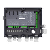
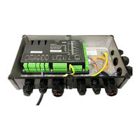
Bitzer CM-RC-01 Manuals
Manuals and User Guides for Bitzer CM-RC-01. We have
6
Bitzer CM-RC-01 manuals available for free PDF download: Maintenance Instructions Manual, Reference Manual, Manual
Bitzer CM-RC-01 Maintenance Instructions Manual (48 pages)
Brand:
Bitzer
| Category:
Control Unit
| Size: 2 MB
Table of Contents
English
2
Table of Contents
2
1 Introduction
3
2 Safety
3
Also Observe the Following Technical Documents
3
Authorized Staff
3
Residual Risks
3
Safety References
3
General Safety References
3
3 Mounting the CM-RC-01 Basic Kit
4
Opening the Cable Bushing on the Terminal Box
4
Removing the SE-B* Motor Protection Device
5
Unscrewing the Terminal Box from the Compressor
5
Mounting the Fixture of the Compressor Module
6
Fastening the Cable Conduit to the Terminal Box
6
Screwing the Compressor Module Onto the Fixture
7
Connecting the Oil Heater
7
Mounting the Discharge Gas Temperature Sensor
8
Mounting the Oil Monitoring
8
Further Electrical Connections on the CM-RC-01
10
Closing the Module Housing
10
Mounting the Cable Holders and Laying the Cables
10
4 Mounting the Optional CM-RC-01 Extension Kits
11
Mounting the Extension Kit "Capacity Control" (CRII) and "Start Unloading" (SU)
11
Mounting the "Pressure Transmitter" Extension Kit
13
Mounting the "Additional Fan" Extension Kit
14
5 Communication Via BEST SOFTWARE
15
Configuration Via BEST SOFTWARE
16
Deutsch
17
1 Einleitung
18
2 Sicherheit
18
Zusätzlich Folgende Technische Dokumente Beachten
18
Autorisiertes Fachpersonal
18
Restgefahren
18
Sicherheitshinweise
18
Allgemeine Sicherheitshinweise
18
3 Montage des CM-RC-01 Basis-Bausatzes
19
Kabeldurchführung am Anschlusskasten Öffnen
19
Motorschutzgerät SE-B* Entfernen
20
Anschlusskasten vom Verdichter Abschrauben
20
Halterung des Verdichtermoduls Montieren
21
Kabelschlauch am Anschlusskasten Befestigen
21
Verdichtermodul auf die Halterung Schrauben
22
Ölheizung Anschließen
22
Druckgastemperaturfühler Montieren
23
Ölüberwachung Montieren
23
Weitere Elektrische Anschlüsse am CM-RC-01
25
Modulgehäuse Schließen
25
Kabelhalter Montieren und Kabel Verlegen
25
Erweiterungsbausatz "Leistungsregelung" (CRII) und "Anlaufentlastung" (SU) Montieren
26
Erweiterungsbausatz "Druckmessumformer" Montieren
28
Erweiterungsbausatz "Zusatzventilator" Montieren
29
5 Kommunikation über die BEST SOFTWARE
30
Konfiguration mit der BEST SOFTWARE
31
Français
32
1 Introduction
33
2 Sécurité
33
Tenir Également Compte de la Documentation Technique Suivante
33
Personnel Spécialisé Autorisé
33
Dangers Résiduels
33
Indications de Sécurité
33
Indications de Sécurité Générales
33
Ouvrir Le Passage de Câble Sur la Boîte de Raccordement
34
Démonter Le Dispositif de Protection SE-B
35
Dévisser la Boîte de Raccordement
35
Monter Le Support de Fixation du Module
36
Fixer Le Conduit de Câbles À la Boîte de Raccordement
36
Visser Le Module du Compresseur Au Support de Fixation
37
Raccorder Le Réchauffeur D'huile
37
Monter la Sonde de Température du Gaz de Refoulement
38
Monter Le Dispositif de Contrôle D'huile
38
Autres Connexions Électriques Sur Le CM-RC-01
40
Fermer Le Boîtier du Module
40
Monter Le Porte-Câbles Et Poser Les Câbles
40
4 Montage des Kits D'extension Optionnels du CM-RC-01
41
Monter Les Kits D'extension " Régulation de Puissance " (CRII) Et " Démarrage À Vide " (SU)
41
Monter Le Kit D'extension " Transmetteurs de Pression
43
Monter Le Kit D'extension " Ventilateur Additionnel
44
5 Communication Via BEST SOFTWARE
45
Configuration Avec BEST SOFTWARE
46
Advertisement
Bitzer CM-RC-01 Reference Manual (44 pages)
Compressor Control Module
Brand:
Bitzer
| Category:
Control Unit
| Size: 1 MB
Table of Contents
Table of Contents
2
Read this First
4
Reference Guide
5
Safety
5
General
6
Definitions
7
Functions
8
Control Functions
8
Motor Start
8
Oil Heater
9
Cylinder Head and Motor Cooling
9
Capacity Control
10
Monitoring and Diagnosis
10
Motor Temperature
10
Discharge Temperature
11
Oil Supply
11
High Pressure Handling
11
Pressure Limits (Option)
11
Application Limits (Option)
12
Short-Cycling Warning
13
Datalog
13
Alarms
14
Events
14
Datalog Information
14
Periodic Data
14
Statistics and Counters
14
Accumulated Operation Counters
15
Capacity Load
15
Daily Counters
15
Runtime Statistic
15
Compressor Start Statistic
15
BEST Software
16
Communication
16
Control of the CM
17
Commands and Setpoint
17
Command Start
17
Setpoint - and Speed Changes
17
Enable Serial Control
18
Required Signals to Start the Compressor
18
Digital and Analogue Signals
18
Serial Control (Modbus)
18
Control Word Bit Definitions
18
Data Valid Bit
19
Examples of Serial Control Word Setups
19
Status Word Bit Definitions
19
Setting the Serial Setpoint
20
Serial Control Timeout Function
20
I/O List for CM
21
Drawings
23
Standards
24
Alarm System
25
Alarm Severity Types
25
Fault Reset Types
25
Alarm List
26
Programming and Monitoring
29
Introduction
29
Serial Communication
29
Modbus (RTU) Configuration
29
Data Values, Scaling and Data Types
30
Reading and Writing 32 Bit Values Via Modbus
30
Modbus Function Codes
30
Modbus Exception Codes
31
Parameters
31
Control - Application
31
Status - Alarm
32
Status - Compressor
33
Status - Motor
34
Status - Device
35
Status - IO
35
Configuration - Application
35
Configuration - Compressor
36
Configuration - COM1
37
Logs - Application
37
Info - Compressortype
37
Trouble Shooting
39
Communications Trouble Shooting
39
Status Leds
40
LED Flashing Patterns of the Three Operation Status Leds
40
Notes
43
Bitzer CM-RC-01 Maintenance Instructions Manual (51 pages)
Instructions for mounting the add-on kit
Brand:
Bitzer
| Category:
Control Unit
| Size: 2 MB
Table of Contents
English
2
Table of Contents
2
1 Introduction
3
2 Safety
3
Also Observe the Following Technical Documents
3
Authorized Staff
3
Residual Risks
3
Safety References
3
General Safety References
3
3 Mounting the CM-RC-01 Basic Kit
4
Mounting the Cable Holders
4
Removing the SE-B* Motor Protection Device
4
Connecting the Oil Heater
4
Mounting the Discharge Gas Temperature Sensor
4
Mounting the Oil Monitoring
4
Further Electrical Connections on the CM-RC-01
8
Screwing the Cover Onto the Module Housing
8
Laying the Cables
9
4 Mounting the Optional CM-RC-01 Extension Kits
10
Mounting the Extension Kit "Capacity Control" (CRII) and "Start Unloading" (SU)
10
Mounting the "Pressure Transmitter" Extension Kit
11
Mounting the "Liquid Injection" Extension Kit
13
Mounting the "Additional Fan" Extension Kit
14
5 Communication Via BEST SOFTWARE
16
Configuration Via BEST SOFTWARE
16
Deutsch
18
1 Einleitung
19
2 Sicherheit
19
Zusätzlich Folgende Technische Dokumente Beachten
19
Autorisiertes Fachpersonal
19
Restgefahren
19
Sicherheitshinweise
19
Allgemeine Sicherheitshinweise
19
3 Montage des CM-RC-01 Basis-Bausatzes
20
Kabelhalter Montieren
20
Motorschutzgerät SE-B* Entfernen
21
Ölheizung Anschließen
22
Druckgastemperaturfühler Montieren
22
Ölüberwachung Montieren
23
Weitere Elektrische Anschlüsse am CM-RC-01
24
Deckel auf das Modulgehäuse Schrauben
24
Kabel Verlegen
25
Erweiterungsbausatz "Leistungsregelung" (CRII) und "Anlaufentlastung" (SU) Montieren
26
Erweiterungsbausatz "Druckmessumformer" Montieren
27
Erweiterungsbausatz "Zusatzventilator" Montieren
30
5 Kommunikation über die BEST SOFTWARE
32
Konfiguration mit der BEST SOFTWARE
32
Français
34
1 Introduction
35
2 Sécurité
35
Tenir Également Compte de la Documentation Technique Suivante
35
Personnel Spécialisé Autorisé
35
Dangers Résiduels
35
Indications de Sécurité
35
Indications de Sécurité Générales
35
Monter Les Porte-Câbles
36
Démonter Le Dispositif de Protection SE-B
36
Raccorder Le Réchauffeur D'huile
36
Monter la Sonde de Température du Gaz de Refoulement
38
Monter Le Dispositif de Contrôle D'huile
39
Autres Connexions Électriques Sur Le CM-RC-01
40
Visser Le Couvercle Sur Le Boîtier du Module
40
Poser Les Câbles
41
4 Montage des Kits D'extension Optionnels du CM-RC-01
42
Monter Les Kits D'extension « Régulation de Puissance » (CRII) Et « Démarrage À Vide » (SU)
42
Monter Le Kit D'extension « Transmetteurs de Pression
43
Monter Le Kit D'extension « Injection de Fluide Frigorigène
46
Monter Le Kit D'extension « Ventilateur Additionnel
47
5 Communication Via BEST SOFTWARE
49
Configuration Avec BEST SOFTWARE
49
Advertisement
Bitzer CM-RC-01 Maintenance Instructions Manual (45 pages)
Brand:
Bitzer
| Category:
Racks & Stands
| Size: 2 MB
Table of Contents
Deutsch
2
Table of Contents
2
1 Einleitung
3
2 Sicherheit
3
Zusätzlich Folgende Technische Dokumente Beachten
3
Autorisiertes Fachpersonal
3
Restrisiken
3
Sicherheitshinweise
3
Allgemeine Sicherheitshinweise
3
3 Montage des CM-RC-01 Basis-Bausatzes
4
Kabelhalter Montieren
4
Motorschutzgerät SE-B* Entfernen
5
Ölheizung
6
Druckgastemperaturfühler Montieren
6
Ölüberwachung Montieren
7
Weitere Elektrische Anschlüsse am CM-RC-01
7
Kabel Verlegen
7
Deckel auf das Modulgehäuse Schrauben
8
Erweiterungsbausatz "Leistungsregelung" (CRII) und "Anlaufentlastung" (SU) Montieren
9
Erweiterungsbausatz "Druckmessumformer" Montieren
10
Erweiterungsbausatz "Kältemitteleinspritzung" Montieren
11
Erweiterungsbausatz "Zusatzventilator" Montieren
13
5 Kommunikation über die BEST SOFTWARE Aufbauen
14
Konfiguration mit der BEST SOFTWARE
15
English
16
1 Introduction
17
2 Safety
17
Also Observe the Following Technical Documents
17
Authorized Staff
17
Residual Risks
17
Safety References
17
General Safety References
17
3 Mounting the CM-RC-01 Basic Kit
18
Mounting the Cable Holders
18
Removing the SE-B* Motor Protection Device
18
Mounting the Discharge Gas Temperature Sensor
18
Mounting the Oil Monitoring Device
18
Further Electrical Connections on the CM-RC-01
21
Laying the Cables
21
Screwing the Cover Onto the Module Housing
22
4 Mounting the Optional CM-RC-01 Extension Kits
22
Mounting the Extension Kit "Capacity Control" (CRII) and "Start Unloading" (SU)
22
Mounting the "Pressure Transmitter" Extension Kit
23
Mounting the "Liquid Injection" Extension Kit
25
Mounting the "Additional Fan" Extension Kit
27
5 Establishing Communication Via the BEST SOFTWARE
28
Configuration Via BEST SOFTWARE
29
Français
30
1 Introduction
31
2 Sécurité
31
Tenir Également Compte de la Documentation Technique Suivante
31
Personnel Spécialisé Autorisé
31
Risques Résiduels
31
Indications de Sécurité
31
Indications de Sécurité Générales
31
Monter Les Porte-Câbles
32
Démonter Le Dispositif de Protection SE-B
32
Réchauffeur D'huile
34
Monter la Sonde de Température du Gaz de Refoulement
34
Monter Le Dispositif de Contrôle D'huile
35
Autres Connexions Électriques Sur Le CM-RC-01
35
Poser Les Câbles
35
Visser Le Couvercle Sur Le Boîtier du Module
36
4 Montage des Kits D'extension Optionnels du CM-RC-01
36
Monter Les Kits D'extension " Régulation de Puissance " (CRII) Et " Démarrage À Vide " (SU)
37
Monter Le Kit D'extension " Transmetteurs de Pression
38
Monter Le Kit D'extension " Injection de Fluide Frigorigène
39
Monter Le Kit D'extension " Ventilateur Additionnel
41
5 Établissement de la Communication Via BEST SOFTWARE
42
Configuration Avec BEST SOFTWARE
43
Bitzer CM-RC-01 Maintenance Instructions Manual (40 pages)
Brand:
Bitzer
| Category:
Control Unit
| Size: 3 MB
Table of Contents
English
2
Table of Contents
2
1 Introduction
3
2 Safety
3
Also Observe the Following Technical Documents
3
Authorized Staff
3
Residual Risks
3
Safety References
3
General Safety References
3
3 Mounting the CM-RC-01 Basic Kit
4
Mounting the Cable Holders
5
Removing the SE-B* Motor Protection Device
5
Oil Heater
7
Mounting the Discharge Gas Temperature Sensor
7
Mounting the DP1 Oil Monitoring Device
8
Further Electrical Connections on the CM-RC-01
9
Laying the Cables
9
Screwing the Cover Onto the Module Housing
10
4 Mounting the Optional CM-RC-01 Extension Kits
10
Mounting the Extension Kit "Capacity Control" (CRII) and "Start Unloading" (SU)
11
Mounting the "Pressure Transmitter" Extension Kit
12
Mounting the "Liquid Injection" Extension Kit
13
Mounting the "Additional Fan" Extension Kit
16
5 Communication Via BEST SOFTWARE
18
Configuration Via BEST SOFTWARE
19
Deutsch
20
1 Einleitung
21
2 Sicherheit
21
Zusätzlich Folgende Technische Dokumente Beachten
21
Autorisiertes Fachpersonal
21
Restgefahren
21
Sicherheitshinweise
21
Allgemeine Sicherheitshinweise
21
3 Montage des CM-RC-01 Basis-Bausatzes
22
Kabelhalter Montieren
23
Motorschutzgerät SE-B* Entfernen
23
Ölheizung
25
Druckgastemperaturfühler Montieren
25
Ölüberwachung DP1 Montieren
26
Weitere Elektrische Anschlüsse am CM-RC-01
27
Kabel Verlegen
27
Deckel auf das Modulgehäuse Schrauben
28
Erweiterungsbausatz "Leistungsregelung" (CRII) und "Anlaufentlastung" (SU) Montieren
29
Erweiterungsbausatz "Druckmessumformer" Montieren
30
Erweiterungsbausatz "Kältemitteleinspritzung" Montieren
31
Erweiterungsbausatz "Zusatzventilator" Montieren
34
5 Kommunikation über die BEST SOFTWARE
36
Konfiguration mit der BEST SOFTWARE
37
Bitzer CM-RC-01 Manual (32 pages)
Brand:
Bitzer
| Category:
Air Compressor
| Size: 2 MB
Table of Contents
Table of Contents
2
Указания По Технике Безопасности
3
Общие Указания По Технике Безопасности
4
3 Технические Данные
4
Minimale Ölniveau-Überwa- Chung
4
Чертежи С Указанием Размеров
6
Варианты Исполнения
6
4 Функции Контроля И Управления
7
Функции Контроля И Защиты
7
Функции Управления
7
5 ЭлектрическоеПодключение
8
Электрическое Подключение
8
Принципиальная Эл. Схема Для Пуска С Разделенными Обмотками
8
Условные Обозначения На Принципиальных Эл. Схемах
8
Seite der Opto-Elektronischen ein Heit Функция Пуска Мотора
11
Кабельные Подключения В Состоянии Поставки
11
Реле Высокого Давления
11
6 Подключение Кабелей
11
Die Schaltung kann über eine Reset-Необходимые Эл. Подключения К Модулю CM-RC-01
12
Опциональные Эл. Подключения
12
Управление CRII-Системой При Помощи Контроллера Системы
13
(Anschluss Siehe Prinzipschaltbild.) 6.3.1 Управление Через Аналоговый Сигнал
13
Управление Через Modbus-Интерфейс
13
Подключение Модуля Управления К BEST Software
13
7 Защитные Функции
13
8 Контроль Рабочих Параметров С Помощью Best Software
14
Обмен Данными Через BEST Software
14
Конфигурирование CM-RC-01 С Помощью BEST Software
14
Настройка Текущего Времени
15
Проверка Функции Запуска Мотора
15
Активация Контроля Области Применения
15
Журнал Данных
15
Advertisement
Related Products
Bitzer CM-SW-01
Bitzer CSH6563-60
Bitzer CSH6563-60Y
Bitzer CSH6593-60
Bitzer CSH8593-180Y
Bitzer CSH96103-280Y
Bitzer CSW7593-90
Bitzer CSW8573-110
Bitzer CSW8593-140
Bitzer CSW9573-160Y
Bitzer Categories
Air Compressor
Heat Pump
Control Unit
Compressor
Controller
More Bitzer Manuals
Login
Sign In
OR
Sign in with Facebook
Sign in with Google
Upload manual
Upload from disk
Upload from URL