Bitzer CM-RC-01 Reference Manual
Compressor control module
Hide thumbs
Also See for CM-RC-01:
- Maintenance instructions manual (51 pages) ,
- Manual (32 pages) ,
- Maintenance instructions manual (45 pages)
Table of Contents
Advertisement
Advertisement
Table of Contents

Related Manuals for Bitzer CM-RC-01


Summary of Contents for Bitzer CM-RC-01
- Page 1 Reference guide Compressor Control Module CM-RC-01 Compressor Control Module...
-
Page 2: Table Of Contents
Reference guide v. 3.0 Compressor Control Module CM-RC-01 Content Read this first! 1.1 Reference guide 1.2 Safety General Definitions Functions 4.1 Control functions 4.1.1 Motor start 4.1.2 Oil heater 4.1.3 Cylinder head and motor cooling 4.1.4 Capacity control 4.2 Monitoring and diagnosis 4.2.1... - Page 3 Reference guide v. 3.0 Compressor Control Module CM-RC-01 10.1 Introduction 10.2 Serial communication 10.2.1 Modbus (RTU) configuration 10.2.2 Data values, scaling and data types 10.2.3 Reading and writing 32 bit values via Modbus 10.2.4 Modbus function codes 10.2.5 Modbus exception codes 10.3 Parameters...
-
Page 4: Read This First
Reference guide v. 3.0 Compressor Control Module CM-RC-01 Read this first! The contents of this manual are subject to change without further notice. Lodam electronics holds the copyright to this reference guide. The user shall follow any instructions given in this reference guide entirely and not only partly. Any non-following of this reference guide result in exclusion of all warranties, guarantees, and liabilities. -
Page 5: Reference Guide
CM-RC-01 has not been correctly installed. Safety The CM-RC-01 is a protection device and not a safety component according to the Machinery Directive and cannot be used in “medical” or “life support” equipment Before commissioning, the service technician shall ensure that personal safety requirements are met in conformity with the Machinery Directive and local legislation based on safety estimations. -
Page 6: General
Compressor Control Module CM-RC-01 General The compressor control module CM-RC-01 is used for protection, control and diagnosis of primarily reciprocating compressors. It is mounted in its own housing and connected to all the sensors and components mounted on the compressor. -
Page 7: Definitions
Reference guide v. 3.0 Compressor Control Module CM-RC-01 Definitions BEST BEST Software Capacity Regulation Direct On Line (motor start) Electro Static Discharge High Pressure Hardware/electronics. Input / Output (electrical signals in and out of a unit) Low Pressure Modbus Application-layer messaging protocol - http://www.modbus.org/specs.php... -
Page 8: Functions
If the CM-RC-01 is locked due to a faulty situation, an external reset must be performed by either powering off the device for minimum 5 seconds or sending a reset command on the serial bus. If a BEST converter is connected, it must be removed during the power-off as the converter will supply power to the module. -
Page 9: Oil Heater
4.1.3.1 Additional fan The CM-RC-01 will start and stop the additional fan according to the application limits for the compressor and the selected refrigerant. The control algorithm in the CM-RC-01 starts the additional fan if the discharge gas temperature gets too high. -
Page 10: Capacity Control
4.1.3.2 Liquid injection cooling (CIC) CIC is a cooling system to reduce the discharge gas temperature. The control algorithm for the liquid injection cooling in the CM-RC-01 starts the CIC if the discharge gas temperature gets too high. 4.1.4 Capacity control The CM-RC-01 can control the needed capacity of the compressor by controlling the CRII valves. -
Page 11: Discharge Temperature
3.0 Compressor Control Module CM-RC-01 If the CM-RC-01 is locked, an external reset must be performed by either powering off the device for minimum 5 seconds or sending a reset command on the serial bus. When power is turned on to the CM-RC-01 module, the PTC resistance is measured: ... -
Page 12: Application Limits (Option)
Optional pressure transducers are needed. The application limits function monitors if the operating conditions of the compressor is within the safe operation area limits – as shown in the BITZER Software when doing compressor calculations. The BITZER Software can be downloaded from BITZER’s homepage, www.BITZER.de. -
Page 13: Short-Cycling Warning
After a stop due to fault limit, the fault can be reset when the compressor is stopped. If timed resets are enabled, the CM-RC-01 will perform a timed reset otherwise an external reset is required. The CM-RC-01 will start the compressor again if the start command is active or when it is applied again. -
Page 14: Alarms
For faults only Set entries are found. E.g.: 07-11-2015 11:01 3431: High Pressure Switch - Fault - Set When all faults are successfully reset and the CM-RC-01 is no longer in fault state, there is an entry like this: 02-12-2015 10:45 0: No Fault - Fault - Clear Lifetime of alarm entries: 365 days. -
Page 15: Accumulated Operation Counters
Reference guide v. 3.0 Compressor Control Module CM-RC-01 4.3.6 Accumulated operation counters All accumulated since first power up No of PowerUps No of Motor Starts Operating Hours Motor Operating Hours Lifetime: 365 days 4.3.7 Capacity load ... -
Page 16: Best Software
The BEST Software is used for live monitoring of operation conditions, download of datalogs and configuration of the CM-RC-01. The BEST Software can be downloaded from the BITZER homepage, www.bitzer.de. Communication Detailed status information and communication with the system controller is done via the Modbus (RTU) interface. -
Page 17: Control Of The Cm
The Start command becomes active when a start signal is given via digital input or serial control. If the compressor is started too many times per hour, the CM-RC-01 will give a waning but the compressor will be allowed to start The speed of the motor will normally match the setpoint. -
Page 18: Enable Serial Control
Running Note: Please observe max number of starts per hour Control commands can be given to the CM-RC-01 via the Serial Control Word. The bit definitions are shown in the table below. The protocol used is Modbus (RTU). Modbus register definitions are listed in section 10.3 Parameters. -
Page 19: Data Valid Bit
To start the compressor, the control word must be 47F hex (= 1151 dec = 10001111111 binary) To disable this interface: Please see section 10.3.7 Configuration – application. In the status word the actual status of the CM-RC-01 can be seen. Status Word bit definitions... -
Page 20: Setting The Serial Setpoint
1: Start command is given (e.g. start signal is given, setpoint > 0 %) and Operation is enabled Critical 0: No critical present 1: A critical is present. The CM-RC-01 is close at its limits and may soon stop the compressor Reserved Setting the serial setpoint... -
Page 21: I/O List For Cm
Type/ Connector Name Logic Description Function Supply Supply for CM-RC-01 and control outputs; Supply 115 V-230 V; +10% ~ -15%, 50/60 Hz; max 500 VA with external components Fuse 8A T @115VAC; 4A T@230VAC K1 Ctrl Motor Activate K1 contactor Start 115 V-230 V;... - Page 22 Reference guide v. 3.0 Compressor Control Module CM-RC-01 Type/ Connector Name Logic Description Function +5V Supply Supply +5 VDC; max 10 mA Signal Input Pressure 1 - 35 bar abs.; 0 - 5V ratio metric; accuracy ±1% F.S. Psuc Ground CN12 Suction pressure.
-
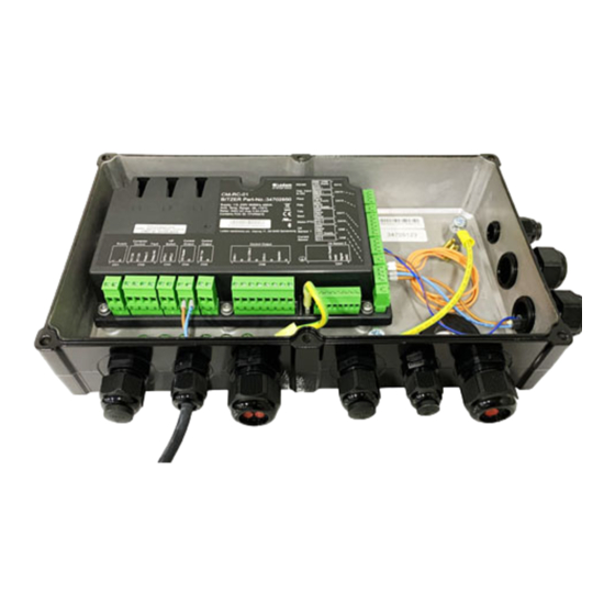
Page 23: Drawings
Reference guide v. 3.0 Compressor Control Module CM-RC-01 Drawings Mounting is inside a new element for the terminal box. Size of the element depends on the compressor model. 23 / 44... -
Page 24: Standards
Reference guide v. 3.0 Compressor Control Module CM-RC-01 Standards The product is manufactured according to the following standards. RoHS 2002/95/EC Low voltage 206/95/EC 61010-1 Safety requirement for electrical equipment for measurement and control EMC 2004/108/EC ... -
Page 25: Alarm System
There are the following alarm severity types: Fault: If a fault-level alarm condition is detected, the CM-RC-01 will open the relays for the motor contacts and stop the compressor motor. A fault is logged in the fault log. -
Page 26: Alarm List
Reference guide v. 3.0 Compressor Control Module CM-RC-01 Alarm list Reset Text Warning Critical Fault type 10-* System - Operation 1000 Too many identical timed reset faults in 24 hours Extern 1001 Too many timed reset faults in 1 hour... - Page 27 Reference guide v. 3.0 Compressor Control Module CM-RC-01 Reset Text Warning Critical Fault type 3400 Suction Pressure Low Timed 3411 Discharge Pressure High Timed 3431 High Pressure Switch Extern 35-* Compressor - Other Input 3500 Oil Level Low Extern 3502...
- Page 28 Reference guide v. 3.0 Compressor Control Module CM-RC-01 Reset Text Warning Critical Fault type 7403 Sensor: Suction Pressure Signal Low Timed 7404 Sensor: Suction Pressure Signal High Timed 7405 Sensor: Discharge Pressure Signal Low Timed 7406 Sensor: Discharge Pressure Signal High...
-
Page 29: Programming And Monitoring
For monitoring and controlling the CM-RC-01, there is a built-in Modbus (RTU) interface. 10.2 Serial communication Communication with the CM-RC-01 is via Modbus (RTU). Configuration and reading of status from the CM-RC-01 is described in the following sections. CM-RC-01 (Slave) System controller (Master) 10.2.1... -
Page 30: Data Values, Scaling And Data Types
Reference guide v. 3.0 Compressor Control Module CM-RC-01 10.2.2 Data values, scaling and data types Following is a description of used scaling and data types. Scale 1, 10 and 100 refers to where the decimal point is implied, as a decimal value cannot be transmitted via Modbus. -
Page 31: Modbus Exception Codes
Reference guide v. 3.0 Compressor Control Module CM-RC-01 10.2.5 Modbus exception codes Code Name Meaning Illegal function The function code is not valid. Illegal data address The specified register is not valid Illegal data value The value is not allowed Slave device failure Unrecoverable error in slave. -
Page 32: Status - Alarm
Reference guide v. 3.0 Compressor Control Module CM-RC-01 Status – alarm 10.3.2 The group contains information about current state of alarms. Modbus Possible Name Default Description type & addr values IR 11100 Number of active unit None Number of active alarms... -
Page 33: Status - Compressor
Reference guide v. 3.0 Compressor Control Module CM-RC-01 Modbus Possible Name Default Description type & addr values IR 11210 AlarmStatus.Alarm10 unit None (AlarmStatus.Alarm10) scale 1 uint16 Status – compressor 10.3.3 The group contains status information for the compressor. Modbus Possible... -
Page 34: Status - Motor
Reference guide v. 3.0 Compressor Control Module CM-RC-01 Modbus Possible Name Default Description type & addr values IR 12027 Motor start is unit None Motor start is requested requested scale 1 (0=Off, 1=On) (Input.StartActive) uint8 IR 12028 Head cooling fan... -
Page 35: Status - Device
None System operating state (System.State) scale 1 (0=CONFIG, 1=INPUT, 2=STARTUP, 3=READY, uint8 4=SUSPEND, 5=SERVICE, 6=PRODUCTION) Status – IO 10.3.6 The group contains status information for I/O of the CM-RC-01. Modbus Possible Name Default Description type & addr values IR 15150... -
Page 36: Configuration - Compressor
Reference guide v. 3.0 Compressor Control Module CM-RC-01 Modbus Possible Name Default Description type & addr values HR 20102 Hour and Minute 0 - 5947 Hour and Minute (DateAndTime.HourMinut scale 1 uint16 HR 20103 Millisecond 0 ms - 0 ms Millisecond (DateAndTime.MilliSec) -
Page 37: Configuration - Com1
Reference guide v. 3.0 Compressor Control Module CM-RC-01 Configuration – COM1 10.3.9 The group contains information for the serial communication. Modbus Possible Name Default Description type & addr values HR 65409 COM1 Address 1 - 247 Device address for Modbus connection (COM1.Address) - Page 38 Reference guide v. 3.0 Compressor Control Module CM-RC-01 Modbus Possible Name Default Description type & addr values 5144=4NES-20(Y), 5145=4JE-13Y, 5146=4JE- 15(Y), 5147=4JE-22(Y), 5148=4HE-15Y, 5149=4HE-18(Y), 5150=4HE-25(Y), 5151=4GE-20Y, 5152=4GE-23(Y), 5153=4GE- 30(Y), 5154=4FE-25Y, 5155=4FE-28(Y), 5156=4FE-35(Y), 5157=6JE-22Y, 5158=6JE- 25(Y), 5159=6JE-33(Y), 5160=6HE-25Y, 5161=6HE-28(Y), 5162=6HE-35(Y), 5163=6GE-30Y, 5164=6GE-34(Y), 5165=6GE-...
-
Page 39: Trouble Shooting
Please observe that all registers in the parameters are index based, meaning they start with no. 1 and not with zero. Use BEST Software for viewing Modbus communication status. Return codes from Modbus communication if a telegram is not accepted by the CM-RC-01. Code Name... -
Page 40: Status Leds
Reference guide v. 3.0 Compressor Control Module CM-RC-01 11.2 Status LEDs There are four LEDs, one LED for communication and three status LEDs. They are visible through the sight glass on the side of the terminal box. LED Status Operation Mode... - Page 41 Reference guide v. 3.0 Compressor Control Module CM-RC-01 o If the unit is started in normal operation mode the green LED will be constant ON. o If the unit is started in Service mode the green LED will be flashing slowly with a short on period.
- Page 42 Reference guide v. 3.0 Compressor Control Module CM-RC-01 Fault (Restart / power cycle) Start-up state - init ressources - init subscribtions - init configuration - init config ready Terminate state, asserts and exceptions Assert in code NMI fault (exception) Hard fault (exception)
-
Page 43: Notes
Reference guide v. 3.0 Compressor Control Module CM-RC-01 Notes ................ - Page 44 Reference guide v. 3.0 Compressor Control Module CM-RC-01 BITZER Kühlmaschinenbau GmbH Eschenbrünnlestraße 15 // 71065 Sindelfingen // Germany Tel +49 (0) 70 31 932-0 // Fax +49 (0) 70 31 932-147 bitzer@bitzer.de // Internet: www.bitzer.de 44 / 44...
Need help?
Do you have a question about the CM-RC-01 and is the answer not in the manual?
Questions and answers