Sign In
Upload
Manuals
Brands
Basler Manuals
Control Systems
DECS-100
Basler DECS-100 Manuals
Manuals and User Guides for Basler DECS-100. We have
2
Basler DECS-100 manuals available for free PDF download: Instruction Manual
Basler DECS-100 Instruction Manual (78 pages)
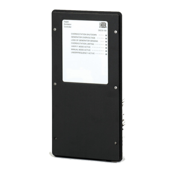
Digital Excitation Control System
Brand:
Basler
| Category:
Control Systems
| Size: 2 MB
Table of Contents
Section 1 • General Information
7
Table of Contents
7
Section 1 • General Information
8
General
8
Features
8
Model and Style Number Description
8
Style Number
8
Specifications
9
Accessory Input
9
Bus Voltage Sensing (Optional)
9
Communication Port
9
Contact Input Circuits
9
Figure 1-1. DECS-100 Style Chart
9
Generator Current Sensing
9
Generator Voltage Sensing
9
Operating Power
9
AVR Operating Mode
10
Common Alarm Output
10
FCR (Manual) Operating Mode
10
Field Output
10
Field Overcurrent Protection
10
Field Overvoltage Protection
10
Generator Overvoltage Protection
10
Parallel Compensation
10
PF Operating Mode (Optional)
10
Var Operating Mode (Optional)
10
CE Compliance
11
CSA Certification
11
Environment
11
Patent
11
Physical
11
Type Tests
11
UL Recognition
11
Section 2 • Human-Machine Interface
12
Section 2 • Human-Machine Interface
13
General
13
Front Panel Indicators
13
Table 2-1. DECS-100 Front Panel Indicator Descriptions
13
Communication Port
14
Section 4 • Installation
22
General
23
Mounting
23
Section 4 • Installation
23
Connections
26
DECS-100 Terminations
26
Bus Voltage Sensing Inputs (Optional)
27
Generator Voltage Sensing Inputs
27
Phase B Line Current Sensing Input
27
Accessory Input
27
Raise and Lower Contact Inputs
27
Var/Power Factor Control Contact Input (Optional)
27
Parallel Generator Compensation
27
Voltage Matching (Optional)
27
Power Supply Inputs
28
Chassis Ground
28
Power (Field) Output
28
Relay Output
28
Communication Port
28
DECS-100 Connections for Typical Applications
29
Installation for Ce Compliance
29
Mounting
29
Wiring
29
Adjustments
34
Preliminary Setup
34
Section 5 • Bestcoms Software for the Windows Operating System
35
Installation
37
Installing BESTCOMS-DECS100-32
37
Connecting the DECS-100 and PC
37
Introduction
37
Operating System
37
Starting Bestcoms
37
Establishing Communication
38
Changing Settings
39
Sending and Receiving Settings
39
Sending Settings
39
Receiving Settings
39
Saving Settings to DECS-100 Memory
39
Setting Definitions
39
System Configuration
39
System Settings
40
Setting Adjustments
41
Setpoint Tab
41
Startup Tab
41
Control Gain
42
Control Gain Tab
42
Analysis
44
AVR Tab
45
FCR Tab
45
PF Tab
46
VAR Tab
47
Protection Settings
48
Protection Tab
49
Metering, Operation and Alarms
50
Operation Tab
50
Alarm/Status Tab
52
Pid Data
53
PID Calculation Based on Input Values
54
Adding to the PID List
54
Removing a PID List Record
54
Retrieving Existing Data from the PID List
55
Settings Files
55
Printing Settings Files
55
Saving Settings Files
55
Uploading Settings Files
55
Password Protection
56
Changing the Password
56
Embedded Firmware
57
Updating the Firmware
57
Terminating Communication
57
Section 6 • Bestcoms Software for the Palm os Platform
61
Platform
61
Section 6 • Bestcoms Software for the Palm os Platform
62
Introduction
62
Installation
62
Installing BESTCOMS
62
Connecting the DECS-100 and Handheld
63
Starting Bestcoms
63
Bestcoms Operating Modes
64
Off-Line Mode
64
On-Line Mode
64
Bestcoms Main Screen
65
Changing Settings
66
Navigating through the Setting Groups
66
Alarm and Contact Input Status
67
System Status
67
Basler Electric Contact Information
68
BESTCOMS Version Information
68
Fine Voltage Adjust Buttons
68
Operating Mode Buttons
68
Regulation and Voltage Matching Buttons
68
Bestcoms File Operations Screen
69
Creating a Settings File
69
Sending a Settings File to the DECS-100
69
Deleting User-Created Settings Files
70
Reading Settings from the DECS-100
70
Section 7 • Maintenance and Trouble- Shooting
71
Maintenance and Trouble-Shooting
72
Preventive Maintenance
72
Troubleshooting
72
Generator Voltage Does Not Build
72
Low Generator Output Voltage
73
High Generator Output Voltage
74
Poor Voltage Regulation
74
Generator Output Unstable (Hunting)
75
OVEREXCITATION SHUTDOWN Indicator Is Annunciating
75
LOSS of GENERATOR SENSING Indicator Is Annunciating
75
OVEREXCITATION LIMITING Indicator Is Annunciating
76
UNDERFREQUENCY ACTIVE Indicator Is Annunciating
76
No Droop
76
No Voltage Matching
77
Advertisement
Basler DECS-100 Instruction Manual (85 pages)
DIGITAL EXCITATION CONTROL SYSTEM
Brand:
Basler
| Category:
Control Systems
| Size: 1 MB
Table of Contents
Section 1 • General Information
11
Table of Contents
11
Style Number
13
Figure 1-1. DECS-100 Style Chart
13
Section 1 • General Information
13
Model and Style Number
13
Introduction
13
Features
13
Specifications
14
Operating Power
14
Generator Voltage Sensing
14
Generator Current Sensing
14
Bus Voltage Sensing (Optional)
14
Field Output
15
AVR Operating Mode
15
Accessory Input
15
Common Alarm Output
15
Contact Input Circuits
15
Communication Port
15
Field Overvoltage Protection
16
Figure 1-2. Typical V/Hz Curves
16
Generator Overvoltage Protection
16
FCR (Manual) Operating Mode
16
Parallel Compensation
16
PF Operating Mode (Optional)
16
Var Operating Mode (Optional)
16
Overexcitation Limiter
17
Underexcitation Limiter
17
Soft Start Function (AVR Mode Only)
17
Voltage Matching
17
Metering (BESTCOMS)
17
CE Compliance
18
Agency Recognition
18
Physical
18
Type Tests
18
Environment
18
Section 2 • Human-Machine Interface
19
Table of Contents
19
Section 4 • Installation
33
Introduction
35
Mounting
35
Section 4 • Installation
35
Connections
38
DECS-100 Terminations
38
Accessory Input
39
Bus Voltage Sensing Inputs (Optional)
39
Generator Voltage Sensing Inputs
39
Parallel Generator Compensation
39
Phase B Line Current Sensing Input
39
Raise and Lower Contact Inputs
39
Table 4-1. Bus Voltage Sensing Terminals
39
Table 4-2. Generator Voltage Sensing Terminals
39
Var/Power Factor Control Contact Input (Optional)
39
Chassis Ground
40
Parallel Control and Var/Pf Control Inputs
40
Power (Field) Output
40
Power Supply Inputs
40
Relay Output (Alarm)
40
Table 4-3. 52L/M and 52J/K Control Modes
40
Voltage Matching (Optional)
40
Communication Port
41
DECS-100 Connections for Typical Applications
41
Table 4-4. Communication Port Pin Functions
41
Installation for Ce Compliance
47
Mounting
47
Preliminary Setup
47
Wiring
47
Adjustments
48
Operating Power Considerations During DECS-100 Programming
48
Section 5 • Bestcoms Software
49
Connecting the DECS-100 and PC
51
Installation
51
Installing BESTCOMS
51
Introduction
51
Section 5 • Bestcoms Software
51
Starting Bestcoms
51
Changing Settings
52
Establishing Communication
52
Receiving Settings
53
Saving Settings to DECS-100 Memory
53
Sending and Receiving Settings
53
Sending Settings
53
Setting Definitions
53
System Configuration
53
System Settings
53
Setpoint Tab
54
Setting Adjustments
54
Startup Tab
55
Control Gain
56
Control Gain Tab
56
Analysis
58
AVR Tab
58
FCR Tab
59
PF Tab
60
VAR Tab
61
Protection Settings
62
Protection Tab
63
Limiter Tab
64
Metering, Operation and Alarms
64
Operation Tab
65
Alarm/Status Tab
67
PID Calculation Based on Input Values
68
Pid Data
68
Adding to the PID List
69
Printing Settings Files
69
Removing a PID List Record
69
Retrieving Existing Data from the PID List
69
Settings Files
69
Changing the Password
70
Password Protection
70
Saving Settings Files
70
Uploading Settings Files
70
Embedded Firmware
71
Terminating Communication
71
Updating the Firmware
71
Section 6 • Maintenance and Trouble- Shooting
75
Generator Voltage Does Not Build
77
Preventative Maintenance
77
Section 6 • Maintenance and Troubleshooting
77
Troubleshooting
77
High Generator Output Voltage
78
Low Generator Output Voltage
78
Generator Output Unstable (Hunting)
80
Poor Voltage Regulation
80
Loss of Generator Sensing Indicator Is Annunciating
81
Overexcitation Limiting Indicator Is Annunciating
81
Overexcitation Shutdown Indicator Is Annunciating
81
Underexcitation Limiting Indicator Is Annunciating
81
No Droop
82
Underfrequency Active Indicator Is Annunciating
82
No Voltage Matching
83
Advertisement
Related Products
Basler DECS-400
Basler DECS-250N
Basler DECS-150
Basler DECS-250
Basler DECS-200
Basler DGC-500
Basler DGC-2020
Basler daA2500-14bc
Basler daA1600-60bm
Basler DART BCON FOR LVDS
Basler Categories
Relays
Digital Camera
Controller
Security Camera
Protection Device
More Basler Manuals
Login
Sign In
OR
Sign in with Facebook
Sign in with Google
Upload manual
Upload from disk
Upload from URL