Sign In
Upload
Manuals
Brands
Automationdirect.com Manuals
Controller
DL06
Automationdirect.com DL06 Manuals
Manuals and User Guides for Automationdirect.com DL06. We have
3
Automationdirect.com DL06 manuals available for free PDF download: User Manual
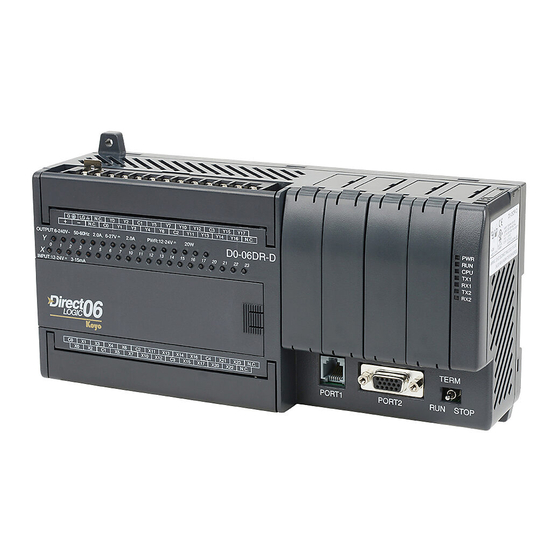
Automationdirect.com DL06 User Manual (382 pages)
Micro PLC
Brand:
Automationdirect.com
| Category:
Controller
| Size: 5 MB
Table of Contents
V T : Olume wo T C Able of
13
Table of Contents
13
Introduction
29
Drum Terminology
30
Introduction
30
Purpose
30
Drum Chart Representation
31
Output Sequences
31
Step Transitions
32
Drum Instruction Types
32
Timer-Only Transitions
32
Timer and Event Transitions
33
Event-Only Transitions
34
Counter Assignments
34
Last Step Completion
35
Overview of Drum Operation
36
Drum Instruction Block Diagram
36
Powerup State of Drum Registers
37
Drum Control Techniques
38
Drum Control Inputs
38
Self-Resetting Drum
39
Initializing Drum Outputs
39
Using Complex Event Step Transitions
39
Drum Instruction
40
Timed Drum with Discrete Outputs (DRUM)
40
Event Drum (EDRUM)
42
Handheld Programmer Drum Mnemonics
44
Masked Event Drum with Discrete Outputs (MDRMD)
47
Masked Event Drum with Word Output (MDRMW)
49
Tage 7 7 7 7 7 7
51
Chapter 7: RLL
52
Introduction to Stage Programming
52
Overcoming "Stage Fright
52
Learning to Draw State Transition Diagrams
53
A 2-State Process
53
Introduction to Process States
53
The Need for State Diagrams
53
RLL Equivalent
54
Stage Equivalent
54
Initial Stages
55
Let's Compare
55
Stage Instruction Characteristics
56
What Stage Bits Do
56
Using the Stage Jump Instruction for State Transitions
57
Stage Jump, Set, and Reset Instructions
57
Stage Program Example: Toggle On/Off Lamp Controller
58
A 4-State Process
58
Four Steps to Writing a Stage Program
59
Draw the Block Diagram
59
Draw the State Transition Diagram
59
Write a Word Description of the Application
59
Write the Stage Program
59
Stage Program Example: a Garage Door Opener
60
Draw the Block Diagram
60
Garage Door Opener Example
60
Draw the State Diagram
61
Add Safety Light Feature
62
Modify the Block Diagram and State Diagram
62
Using a Timer Inside a Stage
63
Add Emergency Stop Feature
64
Emergency Stops
64
Exclusive Transitions
64
Stage Program Design Considerations
65
Stage Program Organization
65
How Instructions Work Inside Stages
66
Stage Counter
67
Using a Stage as a Supervisory Process
67
Power Flow Transition Technique
68
Stage View in Directsoft
68
Parallel Processing Concepts
69
Convergence Stages (CV)
69
Converging Processes
69
Parallel Processes
69
Convergence Jump (CVJMP)
70
Convergence Stage Guidelines
70
RLL PLUS (Stage) Instructions
71
Stage (SG)
71
Initial Stage (ISG)
72
Jump (JMP)
72
Not Jump (NJMP)
72
Converge Stage (CV) and Converge Jump (CVJMP)
73
Block (BLK)
75
Block Call (BCALL)
75
Block End (BEND)
75
Questions and Answers about Stage Programming
77
Ccchapter Hapter Hapter Pid L Oop 8 8 8
79
Chapter 8: PID Loop Operation
80
DL06 PID Control
80
DL06 PID Control Features
80
Introduction to PID Control
82
What Is PID Control
82
Introducing DL06 PID Control
84
Process Control Definitions
86
PID Loop Operation
87
Position Form of the PID Equation
87
Reset Windup Protection
88
Adjusting the Bias
89
Freeze Bias
89
Eliminating Proportional, Integral or Derivative Action
90
Step Bias Proportional to Step Change in SP
90
Velocity Form of the PID Equation
90
Bumpless Transfer
91
Loop Alarms
91
Loop Operating Modes
92
Special Loop Calculations
92
Ten Steps to Successful Process Control
94
PID Loop Setup
96
Establishing the Loop Table Size and Location
96
PID Error Flags
96
Some Things to Do and Know before Starting
96
Loop Table Word Definitions
98
PID Mode Setting 1 Bit Descriptions (Addr + 00)
99
PID Mode Setting 2 Bit Descriptions (Addr + 01)
100
Mode/Alarm Monitoring Word (Addr + 06)
101
Ramp/Soak Table Flags (Addr + 33)
101
Ramp/Soak Table Location (Addr + 34)
102
Ramp/Soak Table Programming Error Flags (Addr + 35)
102
Configure the PID Loop
103
PID Loop Tuning
118
Open-Loop Test
118
Manual Tuning Procedure
119
Alternative Manual Tuning Procedures by Others
122
Tuning PID Controllers
122
Auto Tuning Procedure
123
Open a New Data View Window
127
Use Directsoft 5 Data View with PID View
127
Open PID View
128
Using the Special PID Features
131
How to Change Loop Modes
131
Loop Mode Override
132
Operator Panel Control of PID Modes
132
PLC Modes Effect on Loop Modes
132
PV Analog Filter
133
Creating an Analog Filter in Ladder Logic
134
Filterb Example
135
Use the Directsoft Filter Intelligent Box Instructions
135
Ramp/Soak Generator
136
Introduction
136
Ramp/Soak Table
137
Ramp/Soak Controls
139
Ramp/Soak Generator Enable
139
Ramp/Soak Table Flags
139
Ramp/Soak Profile Monitoring
140
Ramp/Soak Programming Errors
140
Testing Your Ramp/Soak Profile
140
Directsoft Ramp/Soak Example
141
Program the Ramp/Soak Control in Relay Ladder
141
Setup the Profile in PID Setup
141
Test the Profile
142
Cascade Control
143
Introduction
143
Cascaded Loops in the DL06 CPU
144
Tuning Cascaded Loops
145
Time-Proportioning Control
146
On/Off Control Program Example
147
Feedforward Control
148
Feedforward Example
149
PID Example Program
150
Program Setup for the PID Loop
150
Technical Support
152
Troubleshooting Tips
153
Glossary of PID Loop Terminology
155
Bibliography
157
Ccchapter Hapter Hapter M 9 9 9
159
Chapter 9: Maintenance and Troubleshooting
160
Hardware System Maintenance
160
Standard Maintenance
160
Diagnostics
160
Fatal Errors
160
Handheld Programmer
160
Non-Fatal Errors
160
Special Relays (SP) Corresponding to Error Codes
161
Status Indicators
161
V-Memory Error Code Locations
161
DL06 Micro PLC Error Codes
162
Program Error Codes
163
CPU Indicators
164
Communications Problems
165
RUN Indicator
165
I/O Point Troubleshooting
166
Handheld Programmer Keystrokes Used to Test an Output Point
167
Noise Troubleshooting
168
Enclosures
168
Machine Startup and Program Troubleshooting
169
Special Instructions
170
Duplicate Reference Check
171
Comparative Boolean
172
Run Time Edit Example
173
Forcing I/O Points
174
Regular Forcing with Direct Access
176
Bit Override Forcing
177
Reset the PLC to Factory Defaults
178
Ccchapter Hapter Hapter 10 10 10 LCD D P
181
Introduction to the DL06 LCD Display Panel
182
Keypad
182
Chapter 10 : LCD Display Panel
183
Snap-In Installation
183
Display Priority
184
Menu Navigation
185
Confirm PLC Type, Firmware Revision Level, Memory Usage, Etc
186
Menu 2, M2:SYSTEM CFG
188
Examining Option Slot Contents
188
Data Monitor
190
Menu 3, M3:MONITOR
190
Monitoring and Changing Data Values
190
V-Memory Values
190
Pointer Values
192
Bit Monitor
193
Bit Status
193
Changing Date and Time
194
Menu 4, M4 : CALENDAR R/W
194
Menu 5, M5 : PASSWORD R/W
197
Setting Password and Locking
197
Menu 6, M6 : ERR HISTORY
200
Reviewing Error History
200
Menu 7, M7 : LCD TEST&SET
201
Toggle Light and Beeper, Test Keys
201
Data Format Suffixes for Embedded V-Memory Data
202
PLC Memory Information for the LCD Display Panel
202
Reserved Memory Registers for the LCD Display Panel
203
V7742 Bit Definitions
204
Changing the Default Screen
205
Example Program for Setting the Default Screen Message
205
DL06 LCD Display Panel Instruction (LCD)
206
Source of Message
206
ASCII Character Codes
207
Example Program: Alarm with Embedded Date/Time Stamp
208
Example Program: Alarm with Embedded V-Memory Data
209
Example Program: Alarm Text from V-Memory with Embedded V-Memory Data
210
Aaa a a a a F Uxilary Unctions
211
Appendix A: Auxiliary Functions
212
In this Appendix
212
Introduction
212
Purpose of Auxiliary Functions
212
AUX 2* - RLL Operations
212
AUX 3* - V-Memory Operations
212
Accessing aux Functions Via Directsoft
213
Accessing aux Functions Via the Handheld Programmer
213
Aux 2* Rll Operations
213
AUX 21 Check Program
214
AUX 22 Change Reference
214
AUX 23 Clear Ladder Range
214
AUX 24 Clear Ladders
214
AUX 3* - V-Memory Operations
214
AUX 31 Clear V-Memory
214
AUX 4* - I/O Configuration
215
AUX 41 Show I/O Configuration
215
AUX 5* - CPU Configuration
215
AUX 51 Modify Program Name
215
AUX 53 Display Scan Time
215
AUX 54 Initialize Scratchpad
215
AUX 55 Set Watchdog Timer
215
AUX 56 CPU Network Address
216
AUX 57 Set Retentive Ranges
216
AUX 58 Test Operations
216
AUX 59 Bit Override
217
AUX 5B Counter Interface Configuration
217
AUX 5D Select PLC Scan Mode
217
AUX 6* - Handheld Programmer Configuration
218
AUX 61 Show Revision Numbers
218
AUX 62 Beeper On/Off
218
AUX 65 Run Self Diagnostics
218
AUX 7* - EEPROM Operations
218
AUX 71 CPU to HPP EEPROM
218
Transferrable Memory Areas
218
AUX 72 HPP EEPROM to CPU
219
AUX 73 Compare HPP EEPROM to CPU
219
AUX 74 HPP EEPROM Blank Check
219
AUX 75 Erase HPP EEPROM
219
AUX 76 Show EEPROM Type
219
AUX 8* - Password Operations
219
AUX 81 Modify Password
219
AUX 82 Unlock CPU
220
AUX 83 Lock CPU
220
DL06 Error Codes
221
Appendix C: Instruction Execution Times
228
Introduction
228
How to Read the Tables
228
V-Memory Bit Registers
228
V-Memory Data Registers
228
Instruction Execution Times
229
Boolean Instructions
229
Comparative Boolean Instructions
230
Immediate Instructions
237
Bit of Word Boolean Instructions
238
Timer, Counter and Shift Register
239
Accumulator Data Instructions
240
Logical Instructions
241
Math Instructions
242
Bit Instructions
245
Differential Instructions
245
Number Conversion Instructions
246
CPU Control Instructions
248
Interrupt Instructions
248
Network Instructions
248
Program Control Instructions
248
Drum Instructions
249
Intelligent I/O Instructions
249
Message Instructions
249
RLL PLUS Instructions
249
ASCII Instructions
250
Clock/Calendar Instructions
250
MODBUS Instructions
250
Appendix D: Special Relays
252
DL06 PLC Special Relays
252
CPU Operating System
252
CPU Status Relays
252
Startup and Real-Time Relays
252
Accumulator Status
253
Communication Monitoring Relay
254
HSIO Input Status
254
HSIO Pulse Output Relay
254
Option Slot Communication Monitoring Relay
254
Option Slot Special Relay
254
Counter 1 Mode 10 Equal Relays
255
Counter 2 Mode 10 Equal Relays
256
Appendix E: High-Speed Input and Pulse Output Features
258
Introduction
258
Availability of HSIO Features
258
Built-In Motion Control Solution
258
Dedicated High- Speed I/O Circuit
259
Wiring Diagrams for each HSIO Mode
259
Choosing the HSIO Operating Mode
260
Understanding the Six Modes
260
Default Mode
261
Configuring Inputs X0 - X3
262
Configuring the HSIO Mode
262
V–Memory
262
Mode 10: High-Speed Counter
263
Functional Block Diagram
263
Purpose
263
Interfacing to Counter Inputs
264
Wiring Diagram
264
Presets and Special Relays
265
Setup for Mode 10
265
Absolute and Incremental Presets
266
Preset Data Starting Location
267
Using Fewer than 24 Presets
267
Equal Relay Numbers
268
Calculating Your Preset Values
269
Input Configuration
270
Writing Your Control Program
271
Program Example 1: Counter Without Presets
272
Program Example 2: Counter with Presets
274
Program Example 3: Counter with Preload
277
Using Counters
279
Mode 20: Up/Down Counter
280
Quadrature Encoder Signals
281
Interfacing to Encoder Outputs
282
Setup for Mode 20
283
X Input Configuration
284
Writing Your Control Program
285
Program Example 1: Quadrature Counting with an Interrupt
286
Program Example 2: Up/Down Counting with Standard Inputs
288
Program Example 3: Quadrature Counting
290
Troubleshooting Guide for Mode 20
293
Mode 30: Pulse Output
294
Functional Block Diagram
295
Wiring Diagram
296
Motion Profile Specifications
297
Setup for Mode 30
298
Profile/Velocity Select Register
299
Step Trapezoidal Profile
300
Choosing the Profile Type
301
Step Trapezoidal Profiles Defined
302
Automatic Trapezoidal Profile Operation
303
Program Example 1: Automatic Trapezoidal Profile Without External Interrupt
304
Preload Position Value
305
Program Example 2: Automatic Trapezoidal Profile with External Interrupt
306
Program Example 3: Automatic Trapezoidal Profile with Home Search
309
Step Trapezoidal Profile Operation
314
Program Example 4: Step Trapezoidal Profile
315
Velocity Profile Operation
318
Program Example 5: Velocity Profile
319
Automatic Trapezoidal Profile Error Codes
321
Symptom: the Motor Turns in the Wrong Direction
322
Mode 40: High-Speed Interrupts
323
Setup for Mode 40
324
External Interrupt Timing Parameters
325
Program Example 1: External Interrupt
326
Program Example 2: Timed Interrupt
327
Mode 50: Pulse Catch Input
328
Setup for Mode 50
329
X Input Configuration
330
Program Example 1: Pulse Catch
331
Mode 60: Discrete Inputs with Filter
332
Setup for Mode 60
333
Program Example: Filtered Inputs
334
Appendix F: PLC Memory
335
DL06 PLC Memory
335
Appendix G: ASCII Table
339
ASCII Conversion Table
339
Appendix H: Product Weights
341
Product Weight Table
341
Advertisement
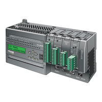
Automationdirect.com DL06 User Manual (533 pages)
Micro Programmable Logic Controller
Brand:
Automationdirect.com
| Category:
Controller
| Size: 12 MB
Table of Contents
Table of Contents
6
Chapter 1: Getting Started
31
Introduction
31
The Purpose of this Manual
31
Supplemental Manuals
31
Technical Support
31
Conventions Used
32
Key Topics for each Chapter
32
DL06 Micro PLC Overview
33
The DL06 PLC Features
33
Directsoft Programming for Windows
33
Handheld Programmer
34
I/O Quick Selection Guide
34
Quick Start
35
Steps to Designing a Successful System
39
Questions and Answers about DL06 Micro Plcs
41
Chapter 2: Installation, Wiring, and Specifications
45
Safety Guidelines
45
Plan for Safety
45
Three Levels of Protection
46
Emergency Stops
46
Emergency Power Disconnect
47
Orderly System Shutdown
47
Class 1, Division 2 Approval
47
Orientation to DL06 Front Panel
48
Terminal Block Removal
49
Mounting Guidelines
50
Unit Dimensions
50
Enclosures
50
Panel Layout & Clearances
51
Using Mounting Rails
52
Environmental Specifications
53
Agency Approvals
53
Marine Use
53
Wiring Guidelines
54
External Power Source
54
Planning the Wiring Routes
55
Fuse Protection for Input and Output Circuits
56
I/O Point Numbering
56
System Wiring Strategies
57
PLC Isolation Boundaries
57
Connecting Operator Interface Devices
58
Connecting Programming Devices
58
Sinking / Sourcing Concepts
59
I/O Common Terminal Concepts
60
Connecting DC I/O to Solid State Field Devices
61
Solid State Input Sensors
61
Solid State Output Loads
61
Relay Output Wiring Methods
63
Relay Outputs-Transient Suppression for Inductive Loads in a Control System
64
Prolonging Relay Contact Life
69
DC Input Wiring Methods
70
DC Output Wiring Methods
71
High-Speed I/O Wiring Methods
72
Wiring Diagrams and Specifications
73
D0-06AA I/O Wiring Diagram
73
D0-06AR I/O Wiring Diagram
75
D0-06DA I/O Wiring Diagram
77
D0-06DD1 I/O Wiring Diagram
79
D0-06DD2 I/O Wiring Diagram
81
D0-06DR I/O Wiring Diagram
83
D0-06DD1-D I/O Wiring Diagram
85
D0-06DD2-D I/O Wiring Diagram
87
D0-06DR-D I/O Wiring Diagram
89
Glossary of Specification Terms
91
Chapter 3: CPU Specifications and Operation
93
Overview
93
DL06 CPU Features
93
CPU Specifications
94
CPU Hardware Setup
95
Communication Port Pinout Diagrams
95
Connecting the Programming Devices
96
CPU Setup Information
96
Status Indicators
97
Mode Switch Functions
97
Changing Modes in the DL06 PLC
98
Mode of Operation at Power-Up
98
Using Battery Backup
99
Battery Backup
99
Auxiliary Functions
100
Clearing an Existing Program
100
Initializing System Memory
100
Setting Retentive Memory Ranges
101
Using a Password
102
CPU Operation
103
CPU Operating System
103
Program Mode
104
Run Mode
104
Read Inputs
105
Service Peripherals and Force I/O
105
CPU Bus Communication
106
Update Clock, Special Relays and Special Registers
106
Solve Application Program
107
Solve PID Loop Equations
107
Write Outputs
107
Write Outputs to Specialty I/O
107
Diagnostics
108
I/O Response Time
108
Is Timing Important for Your Application
108
Normal Minimum I/O Response
109
Normal Maximum I/O Response
109
Improving Response Time
110
CPU Scan Time Considerations
111
Reading Inputs
111
Writing Outputs
111
Service Peripherals
112
CPU Bus Communication
112
Update Clock/Calendar, Special Relays, Special Registers
112
Application Program Execution
113
PLC Numbering Systems
114
PLC Resources
114
V-Memory
115
Binary-Coded Decimal Numbers
115
Hexadecimal Numbers
115
Memory Map
116
Octal Numbering System
116
Discrete and Word Locations
116
V-Memory Locations for Discrete Memory Areas
116
Input Points (X Data Type)
117
Output Points (y Data Type)
117
Control Relays (C Data Type)
117
Timers and Timer Status Bits (T Data Type)
117
Timer Current Values (V Data Type)
118
Word Memory (V Data Type)
119
Stages (S Data Type)
119
DL06 System V-Memory
120
System Parameters and Default Data Locations (V Data Type)
120
DL06 Aliases
122
DL06 Memory Map
123
Input/Y Output Bit Map
124
Stage Control/Status Bit Map
125
Control Relay Bit Map
127
Timer Status Bit Map
129
Counter Status Bit Map
129
GX and GY I/O Bit Map
130
Chapter 4: System Design and Configuration
135
DL06 System Design Strategies
135
I/O System Configurations
135
Networking Configurations
135
Module Placement
136
Slot Numbering
136
Automatic I/O Configuration
137
Manual I/O Configuration
137
Power Budgeting
138
Power Supplied
138
Power Required by Base Unit
138
Power Required by Option Cards
138
Configuring the Dl06'S Comm Ports
140
DL06 Port Specifications
140
DL06 Port Pinouts
140
Choosing a Network Specification
141
RS-232 Network
141
Connecting to MODBUS and Directnet Networks
142
MODBUS Port Configuration
142
Directnet Port Configuration
143
Non-Sequence Protocol (ASCII In/Out and PRINT)
144
Non-Sequence Port Configuration
144
Network Slave Operation
145
MODBUS Function Codes Supported
145
Determining the MODBUS Address
145
If Your Host Software Requires the Data Type and Address
146
Example 1: V2100
147
Example 2: Y20
147
Example 3: T10 Current Value
147
Example 4: C54
147
If Your MODBUS Host Software Requires an Address ONLY
148
Example 1: V2100 584/984 Mode
149
Example 2: Y20 584/984 Mode
149
Example 3: T10 Current Value 484 Mode
150
Example 4: C54 584/984 Mode
150
Network Master Operation
150
Step 1: Identify Master Port # and Slave
151
Step 2: Load Number of Bytes to Transfer
151
Step 3: Specify Master Memory Area
152
Step 4: Specify Slave Memory Area
153
Communications from a Ladder Program
154
Multiple Read and Write Interlocks
154
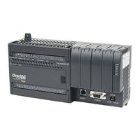
Automationdirect.com DL06 User Manual (278 pages)
Option Modules
Brand:
Automationdirect.com
| Category:
Control Unit
| Size: 8 MB
Table of Contents
Table of Contents
6
Chapter 1: Getting Started
23
Introduction
23
The Purpose of this Manual
23
Supplemental Manuals
23
Technical Support
23
Conventions Used
23
Key Topics for each Chapter
23
Selecting the Proper Module
24
Dl05
24
Dl06
24
Module Choices
24
Module Choices, Continued
25
Installing the Option Modules
26
Remove the Slot Cover
26
Insert the Module
26
Module LED Indicator
27
Power Budgeting
27
Power Supplied
27
Power Required by Base Unit
27
Power Required by Option Cards
27
Chapter 2: Discrete I/O Guidelines
30
Safety Guidelines
30
Plan for Safety
30
Three Levels of Protection
31
Emergency Stops
31
Emergency Power Disconnect
32
Orderly System Shutdown
32
Class 1, Division 2 Approval (Applies ONLY to Modules Used with a DL06 PLC.)
32
System Wiring Strategies
33
PLC Isolation Boundaries
33
I/O "Common" Terminal Concepts
36
Connecting DC I/O to Solid State Field Devices
37
Solid State Input Sensors
37
Solid State Output Loads
37
Relay Output Guidelines
39
Prolonging Relay Contact Life
39
Surge Suppression for Inductive Loads
40
Prolonging Relay Contact Life
41
DC Input Wiring Methods
42
DC Output Wiring Methods
42
Firmware and Software
42
I/O Addressing
43
Module I/O Points and Addressing for the DL05 and DL06
43
All Discrete Modules Installed I/O Addressing Example
44
Discrete and Analog Modules Installed I/O Addressing Example
44
Discrete I/O General Specifications
45
Glossary of Specification Terms
46
F0-08SIM 8-Point Simulator Input Module
47
D0-10ND3 10-Point DC Input Module
48
D0-10ND3F 10-Point DC Fast Input Module
49
D0-16ND3 16-Point DC Input Module
50
F0-08NA-1 8-Point AC Input Module
51
D0-10TD1 10-Point DC Output Module
52
D0-16TD1 16-Point DC Output Module
53
D0-10TD2 10-Point DC Output Module
54
D0-16TD2 16-Point DC Output Module
55
D0-07CDR 4-Point DC Input, 3-Point Relay Output Module
56
D0-08TR 8-Point Relay Output Module
57
D0-08CDD1 4-Point DC Input, 4-Point DC Output Module
58
F0-04TRS 4-Point Relay Output Module
59
Chapter 3: F0-04AD-1, 4-Channel Analog Current Input
61
Module Specifications
61
Setting the Module Jumper
63
Connecting and Disconnecting the Field Wiring
63
Wiring Guidelines
63
Wiring Diagram
64
Current Loop Transmitter Impedance
64
Module Operation
65
Channel Scanning Sequence
65
Analog Module Updates
65
Special V-Memory Locations
66
Formatting the Module Data
66
DL05 Data Formatting
66
Structure of V7700
66
Structure of V7701
66
DL06 Data Formatting
67
Setup Data Type and Number of Channels
67
Storage Pointer Setup
67
Using the Pointer in Your Control Program
68
DL05 Pointer Method
68
DL06 Pointer Method
69
Detecting Input Signal Loss
70
Analog Signal Loss
70
Scale Conversions
70
Scaling the Input Data
70
The Conversion Program
71
Analog and Digital Value Conversions
71
Special Relays
72
DL05 Special Relays
72
DL06 Special Relays
72
Module Resolution
74
Analog Data Bits
74
Resolution Details
74
Analog Input Ladder Logic Filter
75
PID Loops / Filtering
75
Smoothing the Input Signal (DL06 Only)
75
Using Binary Data Format
75
Using BCD Data Format
76
Chapter 4: F0-08ADH-1, 8-Channel Analog Current Input
78
Module Specifications
78
Connecting and Disconnecting the Field Wiring
80
Wiring Guidelines
80
Wiring Diagram
81
Current Loop Transmitter Impedance
81
Module Operation
82
Channel Scanning Sequence
82
Analog Module Updates
82
Special V-Memory Locations
83
Formatting the Analog Module Data
83
DL05 Data Formatting
83
Setup Data Type and Number of Active Channels
83
Storage Pointer Setup
83
DL06 Data Formatting
84
Setup Data Type and Number of Active Channels
84
Storage Pointer Setup
84
Using the Pointer in Your Control Program
85
DL05 Pointer Method Using Conventional Ladder Logic
85
DL05 Pointer Method Using the Ibox Instruction Available in Directsoft5
85
DL06 Pointer Method Using Conventional Ladder Logic
86
DL06 Pointer Method Using the Ibox Instruction Available in Directsoft6
87
Scale Conversions
87
Scaling the Input Data
87
The Conversion Program in Standard Ladder Logic
88
Analog and Digital Value Conversions
89
Module Resolution
90
Analog Data Bits
90
Resolution Details
90
Analog Input Ladder Logic Filter
91
PID Loops / Filtering
91
Smoothing the Input Signal (DL06 Only)
91
Binary Data Format Filter Using Ladder Logic
91
BCD Data Format Filter Using Ladder Logic
92
Example Code to Scale a 4-20 Ma Signal to 0-1000 BCD
93
Example Code to Scale a 4-20 Ma Signal to 0-1000 Binary
94
Chapter 5 - F0-04AD-2, 4-Channel Analog Voltage Input
96
Module Specifications
96
Setting the Module Jumpers
98
Connecting and Disconnecting the Field Wiring
99
Wiring Guidelines
99
Wiring Diagram
99
Module Operation
100
Input Channel Update Sequence
100
Analog Module Updates
100
Special V-Memory Locations
101
Formatting the Module Data
101
DL05 Data Formatting
101
Structure of V7700
101
Structure of V7701
101
DL06 Data Formatting
102
Setup Data Type and Number of Channels
102
Storage Pointer Setup
102
Using the Pointer in Your Control Program
103
DL05 Pointer Method
103
DL06 Pointer Method
104
Scale Conversions
105
Scaling the Input Data
105
The Conversion Program
106
Analog and Digital Value Conversions
107
Module Resolution
108
Analog Data Bits
108
Resolution Details
108
Analog Input Ladder Logic Filter
109
PID Loops / Filtering
109
Smoothing the Input Signal (DL06 Only)
109
Using Binary Data Format
109
Using BCD Data Format
110
Chapter 6: F0-08ADH-2, 8-Channel Analog Voltage Input
112
Module Specifications
112
Setting the Module Jumpers
114
Locating the Jumpers
114
Setting the Appropriate Jumper
114
Connecting and Disconnecting the Field Wiring
115
Wiring Guidelines
115
Wiring Diagram
116
Module Operation
117
Channel Scanning Sequence
117
Analog Module Updates
117
Special V-Memory Locations
118
Formatting the Analog Module Data
118
DL05 Data Formatting
118
Setup Data Type and Number of Active Channels
118
Storage Pointer Setup
118
DL06 Data Formatting
119
Setup Data Type and Number of Active Channels
119
Storage Pointer Setup
119
Using the Pointer in Your Control Program
120
DL05 Pointer Method Using Conventional Ladder Logic
120
DL05 Pointer Method Using the Ibox Instruction Available in Directsoft5
120
DL06 Pointer Method Using Conventional Ladder Logic
121
DL06 Pointer Method Using the Ibox Instruction Available in Directsoft5
122
Scale Conversions
122
Scaling the Input Data
122
The Conversion Program in Standard Ladder Logic
123
Analog and Digital Value Conversions
124
Module Resolution
125
Analog Data Bits
125
Resolution Details
125
Analog Input Ladder Logic Filter
126
PID Loops / Filtering
126
Smoothing the Input Signal (DL06 Only)
126
Binary Data Format Filter Using Ladder Logic
126
Using BCD Data Format
127
Chapter 7: F0-04DAH-1, 4-Channel Analog Current Output
129
Module Specifications
129
Connecting and Disconnecting the Field Wiring
131
Wiring Guidelines
131
Wiring Diagram
132
Module Operation
133
Channel Scanning Sequence
133
Special V-Memory Locations
134
Formatting the Analog Module Data
134
DL05 Data Formatting
134
Data Type and Number of Active Channels Setup
134
Storage Pointer Setup
134
DL06 Data Formatting
135
Data Type and Number of Active Channels Setup
135
Storage Pointer Setup
135
Using the Pointer in Your Control Program
136
DL05 Pointer Method Using Conventional Ladder Logic
136
DL05 Pointer Method Using the Ibox Instruction Available in Directsoft5
136
DL06 Pointer Method Using Conventional Ladder Logic
137
DL06 Pointer Method Using the Ibox Instruction Available in Directsoft5
138
Output Scale Conversion
138
Calculating the Digital Output Value
138
The Conversion Program in Standard Ladder Logic
139
Analog and Digital Value Conversions
140
Module Resolution
141
Analog Data Bits
141
Resolution Details
141
Chapter 8: F0-08DAH-1, 8-Channel Analog Current Output
143
Module Specifications
143
Connecting and Disconnecting the Field Wiring
145
Wiring Guidelines
145
Wiring Diagram
146
Module Operation
147
Channel Scanning Sequence
147
Special System V-Memory Locations
148
Formatting the Analog Module Data
148
DL05 Data Formatting
148
Data Type and Number of Active Channels Setup
148
Storage Pointer Setup
148
DL06 Data Formatting
149
Data Type and Number of Active Channels Setup
149
Storage Pointer Setup
149
Using the Pointer in Your Control Program
150
DL05 Pointer Method Using Conventional Ladder Logic
150
DL05 Pointer Method Using the Ibox Instruction Available in Directsoft6
150
DL06 Pointer Method Using Conventional Ladder Logic
151
DL06 Pointer Method Using the Ibox Instruction Available in Directsoft5
152
Output Scale Conversion
152
Calculating the Digital Output Value
152
The Conversion Program in Standard Ladder Logic
153
Analog and Digital Value Conversions
154
Module Resolution
155
Analog Data Bits
155
Resolution Details
155
Chapter 9: F0-04DAH-2, 4-Channel Analog Voltage Output
157
Module Specifications
157
Connecting and Disconnecting the Field Wiring
159
Wiring Guidelines
159
Wiring Diagram
160
Module Operation
161
Channel Scanning Sequence
161
Special V-Memory Locations
162
Formatting the Analog Module Data
162
DL05 Data Formatting
162
Data Type and Number of Active Channels Setup
162
Storage Pointer Setup
162
DL06 Data Formatting
163
Data Type and Number of Active Channels Setup
163
Storage Pointer Setup
163
Using the Pointer in Your Control Program
164
DL05 Pointer Method Using Conventional Ladder Logic
164
DL05 Pointer Method Using the Ibox Instruction Available in Directsoft6
164
DL06 Pointer Method Using Conventional Ladder Logic
165
DL06 Pointer Method Using the Ibox Instruction Available in Directsoft6
166
Output Scale Conversion
166
Calculating the Digital Output Value
166
The Conversion Program in Standard Ladder Logic
167
Analog and Digital Value Conversions
168
Module Resolution
169
Analog Data Bits
169
Resolution Details
169
Chapter 10: F0-08DAH-2, 8-Channel Analog Voltage Output
171
Module Specifications
171
Connecting and Disconnecting the Field Wiring
173
Wiring Guidelines
173
Wiring Diagram
174
Module Operation
175
Channel Scanning Sequence
175
Special V-Memory Locations
176
Formatting the Analog Module Data
176
DL05 Data Formatting
176
Data Type and Number of Active Channels Setup
176
Storage Pointer Setup
176
DL06 Data Formatting
177
Data Type and Number of Active Channels Setup
177
Storage Pointer Setup
177
Using the Pointer in Your Control Program
178
DL05 Pointer Method Using Conventional Ladder Logic
178
DL05 Pointer Method Using the Ibox Instruction Available in Directsoft6
178
DL06 Pointer Method Using Conventional Ladder Logic
179
DL06 Pointer Method Using the Ibox Instruction Available in Directsoft6
180
Output Scale Conversion
180
Calculating the Digital Output Value
180
The Conversion Program in Standard Ladder Logic
181
Analog and Digital Value Conversions
182
Module Resolution
183
Analog Data Bits
183
Resolution Details
183
Chapter 11 - F0-4AD2DA-1, 4-Channel In/2-Ch. out Analog
185
Module Specifications
185
Setting the Module Jumper
187
Connecting and Disconnecting the Field Wiring
188
Wiring Guidelines
188
Wiring Diagram
189
Current Loop Transmitter Impedance
189
Module Operation
190
Input/Output Channel Update Sequence
190
Analog Module Updates
190
Special V-Memory Locations
191
Formatting the Module Data
191
DL05 Data Formatting
191
Structure of V7700
191
Structure of V7701
191
Structure of V7702
192
DL06 Data Formatting
193
Setup Data Type and Number of Channels
193
Input Storage Pointer Setup
193
Output Storage Pointer Setup
193
Using the Pointer in Your Control Program
194
DL05 Pointer Method
194
DL06 Pointer Method
195
Scale Conversions
196
Scaling the Input Data
196
The Conversion Program
197
Output Conversion Program
197
Analog and Digital Value Conversions
198
Special Relays
199
DL05 Special Relays
199
DL06 Special Relays
199
Module Resolution
201
Analog Data Bits
201
Resolution Details
201
Analog Input Ladder Logic Filter
202
PID Loops / Filtering
202
Smoothing the Input Signal (DL06 Only)
202
Using Binary Data Format
202
Using BCD Data Format
203
Chapter 12 - F0-2AD2DA-2, 2-Channel In/2-Ch. out Analog
205
Module Specifications
205
Setting the Module Jumpers
207
Connecting and Disconnecting the Field Wiring
208
Wiring Guidelines
208
Wiring Diagram
208
Module Operation
209
Input/Output Channel Scanning Sequence
209
Analog Module Updates
209
Special V-Memory Locations
210
Formatting the Module Data
210
DL05 Data Formatting
210
Structure of V7700
210
Structure of V7701
210
Structure of V7702
211
DL06 Data Formatting
212
Setup Data Type and Number of Channels
212
Input Storage Pointer
212
Output Storage Pointer
212
Using the Pointer in Your Control Program
213
DL05 Pointer Method
213
DL06 Pointer Method
214
Scale Conversions
215
Scaling the Input Data
215
The Conversion Program
216
Output Conversion Program
216
Analog and Digital Value Conversions
217
Module Resolution
218
Analog Data Bits
218
Advertisement
Advertisement
Related Products
Automationdirect.com DL05
Automationdirect.com DirectLOGIC DL205 Series
Automationdirect.com D4-454 PLC
Automationdirect.com D4-470
Automationdirect.com DL305
Automationdirect.com GS1-10P2
Automationdirect.com GS1-10P5
Automationdirect.com GS1-20P2
Automationdirect.com GS1-20P5
Automationdirect.com GS1-21P0
Automationdirect.com Categories
I/O Systems
Control Unit
Controller
Temperature Controller
Transducer
More Automationdirect.com Manuals
Login
Sign In
OR
Sign in with Facebook
Sign in with Google
Upload manual
Upload from disk
Upload from URL