Sign In
Upload
Manuals
Brands
AUMA Manuals
Controller
SA 07.1
AUMA SA 07.1 Manuals
Manuals and User Guides for AUMA SA 07.1. We have
5
AUMA SA 07.1 manuals available for free PDF download: Operation Instructions Manual, Operation & Instruction Manual, Operation Instructons
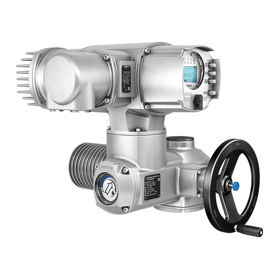
AUMA SA 07.1 Operation Instructions Manual (80 pages)
Multi-turn actuators
Brand:
AUMA
| Category:
Controller
| Size: 1 MB
Table of Contents
Table of Contents
2
1 Safety Instructions
5
Basic Information on Safety
5
Range of Application
5
Applications in Ex Zone 22 (Option)
6
Warnings and Notes
6
References and Symbols
7
2 Identification
8
Name Plate
8
Short Description
9
3 Transport, Storage and Packaging
10
Transport
10
Storage
10
Packaging
10
4 Assembly
11
Mounting Position
11
Handwheel Fitting
11
Multi-Turn Actuator: Mount to Valve/Gearbox
12
Output Drive Types B, B1
12
B4 and E
12
Multi-Turn Actuator
12
B4 or E): Mount to Valve/Gearbox
12
Output Drive Type a
13
Stem Nut: Finish Machining
13
Multi-Turn Actuator (with Output Drive Type A): Mount to Valve
14
Accessories for Assembly
15
Stem Protection Tube for Rising Valve Stem
15
Mounting Positions of Local Controls
15
Mounting Positions: Modify
16
5 Electrical Connection
17
Basic Information
17
Connection with AUMA Plug/Socket Connector
19
Terminal Compartment: Open
19
Cable Connection
20
Terminal Compartment: Close
21
Bus Terminal Compartment: Open
21
Bus Cables: Connect
22
Bus Terminal Compartment: Close
25
Accessories for Electrical Connection
25
Controls Mounted to Wall Bracket
25
Parking Frame
26
Protection Cover
27
Double Sealed Intermediate Frame
27
Earth Connection, External
27
6 Operation
28
Manual Operation
28
Manual Operation: Engage
28
Manual Operation: Disengage
28
Motor Operation
29
Local Operation
29
Operation from REMOTE
30
Menu Navigation Via Push Buttons (for Settings and Indications)
30
Short Overview: Functions of the Push Buttons
31
Structural Design and Navigation
31
Password Entry
32
Language Change in the Display
32
7 Indications
34
Status Indications in the Display
34
Status Indication S0/S6 - Operation
34
Torque Indication: Edit
35
Indication Lights/Leds
35
Mechanical Position Indicator/Running Indication
36
8 Signals
37
Signals Via Fieldbus
37
Feedback Signals Via Output Contacts (Binary)
37
Feedback Signals (Analogue)
37
9 Commissioning (Basic Settings)
38
Heat-Up Time for Low Temperature Version
38
Type of Seating: Check/Edit for End Positions
38
Baud Rate, Parity and Bus Addres (Slave Addess): Set
42
Further Parameters of the Modbus Interface
45
Switch Compartment: Open
45
Torque Switching: Set
46
Limit Switching: Set
46
End Position CLOSED (Black Section): Set
47
End Position OPEN (White Section): Set
47
Intermediate Positions: Set
48
Running Direction CLOSE (Black Section): Set
48
Running Direction OPEN (White Section): Set
48
Test Run
49
Direction of Rotation: Check
49
Limit Switching: Check
50
Reference Operation Position Feedback: Perform
50
Potentiometer Setting
51
Electronic Position Transmitter RWG: Set
51
Mechanical Position Indicator: Set
52
Switch Compartment: Close
53
Corrective Action
54
Faults During Commissioning
54
Fault Indications and Warning Indications
54
Status Indication S0 - Faults and Warnings
55
Status Indication S1 - Faults
55
Status Indication S2 - Warnings
56
Status Indication S3 - Causes for Not Ready Remote
57
Fuses
57
Fuses Within the Actuator Controls
57
Motor Protection (Thermal Monitoring)
58
Servicing and Maintenance
60
Preventive Measures for Servicing and Safe Operation
60
Maintenance
60
Disposal and Recycling
61
Technical Data
62
Features and Functions of Actuator
62
Features and Functions of Actuator Controls
63
Modbus Interface
66
Service Conditions
67
Accessories
68
Further Information
68
Spare Parts
69
Multi-Turn Actuators SA
69
Sa 16.1/Sar 07.1
69
Actuator Controls AUMATIC AC 01.1 with AUMA Plug/Socket Connector (SD Bus)
71
Certificates
73
Declaration of Incorporation and EC Declaration of Conformity
73
Index
76
Addresses
78
Advertisement
AUMA SA 07.1 Operation Instructions Manual (72 pages)
Multi-turn actuator/Intrusive with actuator controls AUMATIC AC 01.1
Brand:
AUMA
| Category:
Controller
| Size: 1 MB
Table of Contents
Table of Contents
2
1 Safety Instructions
5
General Notes on Safety
5
Range of Application
6
Applications in Ex Zone 22 (Option)
7
Warnings and Notes
8
Further References and Symbols
8
2 Identification
9
Name Plate
9
Short Description
11
3 Transport, Storage and Packaging
12
Transport
12
Storage
12
Packaging
12
4 Assembly
13
Handwheel Fitting
13
Multi-Turn Actuator Mounting to Valve/Gearbox
14
Output Drive Types B1, B2, B3, B4, B, and E
14
Output Drive Type a
15
Accessories (Option)
17
Protection Tube for Rising Valve Stem
17
Mounting Positions of the Local Controls
18
5 Electrical Connection
19
General Notes
19
Connection with AUMA Plug/Socket Connector (S, SH, SE)
20
Accessories for Electrical Connection (Option)
23
Controls Mounted to Wall Bracket
23
Parking Frame
24
Protection Cover
24
Double Sealed Intermediate Frame
24
Ground Connection, External
24
6 Operation
25
Manual Operation
25
Motor Operation
26
Local Operation
26
Operation from REMOTE
26
Menu Navigation Via Push Buttons (for Settings and Indications)
27
Short Overview: Functions of the Push Buttons
27
Structural Design and Navigation
28
Language Change in the Display
29
7 Indications
31
Status Indication in the Display
31
Status Indication S0/S6 - Operation
31
Indication Lights/Leds
32
Mechanical Position Indicator/Running Indication (Option)
32
8 Signals
33
Feedback Via Output Contacts (Binary)
33
Feedback Signals (Analogue) - (Option)
33
9 Commissioning
34
Type of Seating: Check/Edit for End Positions
35
Switch Compartment: Open
38
Torque Switching: Check/Set
39
Limit Switching Setting
40
End Position CLOSED (Black Section) Setting
40
End Position OPEN (White Section) Setting
40
Intermediate Positions (Option) Setting
41
Running Direction CLOSE (Black Section) Setting
41
Running Direction OPEN (White Section) Setting
41
Test Run
42
Rotational Direction Check
42
Limit Switching Check
43
Perform Reference Operation
43
Potentiometer (Option) Setting
44
Electronic Position Transmitter RWG Setting (Option)
45
Mechanical Position Indicator Setting (Option)
46
Switch Compartment: Close
47
10 Corrective Action
48
Faults During Commissioning
48
Mechanical Position Indicator
48
Position Transmitter RWG
48
Limit and Torque Switches
48
Fault in End Position (Overrun Not Considered)
49
Push Buttons Do Not React
49
Fault Indications and Warning Indications
50
Status Display S0 - Faults and Warnings
50
Status Indication S1 - Faults
51
Status Indication S2 - Warnings
52
Status Indication S3 - Causes for Not Ready Remote
53
Fuses
54
Fuses Within the Actuator Controls
54
Motor Protection (Thermal Monitoring)
55
11 Servicing and Maintenance
56
Preventive Measures for Servicing and Safe Operation
56
Maintenance
57
Disposal and Recycling
57
12 Spare Parts List
58
Multi-Turn Actuator SA 07.1 - SA 16.1/SAR 07.1 - SAR
58
Controls AC 01.1 with AUMA Plug/Socket Connector (S, SH, SE)
60
13 Technical Data
62
14 Certificates
68
Declaration of Conformity and Declaration of Incorporation
68
Index
69
Addresses
70
AUMA SA 07.1 Operation & Instruction Manual (36 pages)
Electric multi-turn actuators with actuator controls AMB 01.1/AMB 02.1
Brand:
AUMA
| Category:
Controller
| Size: 2 MB
Table of Contents
Table of Contents
2
1 Safety Instructions
4
Commissioning (Electrical Connection)
4
Maintenance
4
Range of Application
4
2 Short Description
4
Warnings and Notes
4
3 Technical Data
5
4 Additional Information to the Wiring Diagram Legend
7
5 Transport and Storage
7
6 Packaging
7
7 Mounting to Valve/ Gearbox
8
8 Manual Operation
10
Connection with AUMA Plug/ Socket Connector
11
9 Electrical Connection
11
Fitting of the Cover
12
Heater
12
Motor Protection
12
Remote Position Transmitter
12
10 Opening the Switch Compartment
13
Pulling off the Indicator Disc (Option)
13
Removal of the Switch Compartment Cover
13
Checking the Switches
14
Setting for End Position CLOSED (Black Section)
14
Setting for End Position OPEN (White Section)
14
11 Setting of the Limit Switching
14
Setting for Direction CLOSE (Black Section)
15
Setting for Direction OPEN (White Section)
15
12 Setting of the DUO Limit Switching (Option)
15
Checking the Switches for Torque and DUO Limit Switching
16
Setting
16
13 Setting of the Torque Switching
16
Check Direction of Rotation
17
14 Test Run
17
Check the Setting of the Limit Switching
18
Check Whether Type of Seating Is Set Correctly
18
15 Setting of the Potentiometer (Option)
18
16 Setting of Electronic Position Transmitter RWG (Option)
19
Setting for 2-Wire System 4 - 20 Ma and 3- /4-Wire System 0 - 20 Ma
20
Setting for 3- / 4- Wire System 4 - 20 Ma
21
17 Setting of the Mechanical Position Indicator (Option)
22
18 Closing the Switch Compartment
22
19 Controls AUMA MATIC BASIC
23
Removal of the Local Controls
23
Setting the Type of Seating in the End Position CLOSED
23
Fitting the Local Controls
24
Push-To-Run Operation or Self-Retaining in Selector Switch Position LOCAL
24
Push-To-Run Operation or Self-Retaining in Selector Switch Position REMOTE
24
Settings on Relay Board for Potential-Free Feedback (Option)
25
20 Fuses
26
21 Maintenance
27
22 Lubrication
27
23 Disposal and Recycling
27
24 Service
27
25 Spare Parts List Multi-Turn Actuator SA 07.1 - SA
30
26 Spare Parts List Controls AUMA MATIC
32
27 Declaration of Conformity and Declaration of Incorporation
34
Index
35
Addresses of AUMA Offices and Representatives
36
Advertisement
AUMA SA 07.1 Operation Instructions Manual (32 pages)
Electric multi-turn actuators. AUMA NORM for flanges type FA
Brand:
AUMA
| Category:
Controller
| Size: 1 MB
Table of Contents
Table of Contents
2
1 Safety Instructions
4
Commissioning (Electrical Connection)
4
Maintenance
4
Range of Application
4
2 Short Description
4
Warnings and Notes
4
3 Technical Data
5
Packaging
7
Storage
7
Transport
7
4 Transport, Storage and Packaging
7
5 Mounting to Valve/Gearbox
8
6 Manual Operation
10
Connection with AUMA Plug/Socket Connector
11
7 Electrical Connection
11
Controls Made by AUMA
12
Delay Time
12
Heater
12
Motor Connection for Special Motors
12
Motor Connection for the Sizes SA(R) 25.1/SAR 30.1 - SA
12
Motor Protection
12
Remote Position Transmitter
12
Fitting of the Cover
13
Limit and Torque Switches
13
8 Opening the Switch Compartment
14
Pulling off the Indicator Disc (Option)
14
Removing the Switch Compartment Cover
14
Checking the Limit Switches
15
Setting the End Position CLOSED (Black Section)
15
Setting the End Position OPEN (White Section)
15
9 Setting the Limit Switching
15
Checking the DUO Switches
16
Setting the Direction CLOSE (Black Section)
16
Setting the Direction OPEN (White Section)
16
10 Setting the DUO Limit Switching (Option)
16
Checking the Torque Switches
17
Setting
17
11 Setting the Torque Switching
17
Check Direction of Rotation
18
Check Limit Switching
18
12 Test Run
18
13 Setting the Potentiometer (Option)
19
14 Setting the Electronic Position Transmitter RWG (Option)
20
Setting for 2-Wire System 4 - 20 Ma and 3-/4-Wire System 0 - 20 Ma
21
Setting the 3-/4- Wire System 4 - 20 Ma
22
AUMA SA 07.1 Operation Instructons (15 pages)
Multi-Turn Actuators
Brand:
AUMA
| Category:
Controller
| Size: 0 MB
Table of Contents
Table of Contents
2
Transport and Storage
6
Service Conditions
6
Mounting to the Valve/Gearbox
6
Manual Operation
7
Electrical Connections
7
Terminal Access
7
Wiring Connections
8
Completion of Electrical Connection
8
Test Run
9
Operating Direction for Test Knobs
9
Setting of Limit Switching
10
Setting the CLOSED End Position
10
Setting the OPEN End Position
10
Setting of DUO Counter Gear or Four Gear Train
10
Setting of Torque Switching
11
Setting of Mechanical Dial Position Indicator
11
Setting of the Potentiometer
12
Setting of the Current Transmitter RWG
12
Machining of Stem Nut, Form a Output Drive
12
Maintenance
13
Advertisement
Related Products
AUMA SA 07.2
AUMA SA 07.1 - SA 30.1
AUMA SA 07.5
AUMA SA 07.6
AUMA SA 07.2-F07
AUMA SA 07.2-UW
AUMA SA 07.6-UW
AUMA SA 15
AUMA SAI 50
AUMA SAVEx 07.6
AUMA Categories
Controller
Industrial Equipment
Control Unit
Control Systems
Outboard Motor
More AUMA Manuals
Login
Sign In
OR
Sign in with Facebook
Sign in with Google
Upload manual
Upload from disk
Upload from URL