Sign In
Upload
Manuals
Brands
AUMA Manuals
Controller
SA 07.1 - SA 30.1
AUMA SA 07.1 - SA 30.1 Actuator Controls Manuals
Manuals and User Guides for AUMA SA 07.1 - SA 30.1 Actuator Controls. We have
1
AUMA SA 07.1 - SA 30.1 Actuator Controls manual available for free PDF download: Operation Instructions Manual
AUMA SA 07.1 - SA 30.1 Operation Instructions Manual (60 pages)
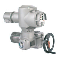
Multi-turn actuators with actuator controls AUMA MATIC AM 01.1; AUMA MATIC AM 02.1
Brand:
AUMA
| Category:
Controller
| Size: 2 MB
Table of Contents
Table of Contents
2
1 Safety Instructions
4
Electrical Connection
4
Maintenance
4
Range of Application
4
Warnings and Notes
4
2 Short Description
5
3 Technical Data
6
4 Additional Information to the Wiring Diagram Legend
9
Packaging
10
Storage
10
Transport
10
5 Transport, Storage and Packaging
10
6 Mounting to Valve/Gearbox
11
7 Mounting Positions of the Local Controls
13
8 Electrical Connection
14
Connection with AUMA Plug/Socket Connector (S, SH, SE)
16
9 Manual Operation
18
10 Operation and Indications of the Local Controls
19
11 Opening the Switch Compartment
21
Pulling off the Indicator Disc (Option)
21
Removing the Cover from the Switch Compartment
21
Checking the Limit Switches
22
Setting End Position CLOSED (Black Section)
22
Setting End Position OPEN (White Section)
22
12 Setting the Limit Switching
22
Checking the DUO Limit Switches
23
Setting Direction CLOSE (Black Section)
23
Setting Direction OPEN (White Section)
23
13 Setting the DUO Limit Switching (Option)
23
Checking the Torque Switches
24
Setting
24
14 Setting the Torque Switching
24
Checking the Direction of Rotation
25
15 Test Run
25
Checking the PTC Tripping Device (Option)
26
Checking the Setting of the Limit Switching
26
Checking the Type of Seating
26
16 Setting the Potentiometer (Option)
27
17 Setting the Electronic Position Transmitter RWG (Option)
28
Setting 2-Wire System 4 - 20 Ma and 3-/4-Wire System 0 - 20 Ma
29
Setting 3-/4- Wire System 4 - 20 Ma
30
18 Setting the Mechanical Position Indicator (Option)
31
19 Closing the Switch Compartment
31
20 Actuator Controls AUMA MATIC
32
Functions of the Diagnosis Leds on the Interface Board (Standard Version)
32
Programming the Logic Board
33
EMERGENCY - OPEN and EMERGENCY - CLOSE Signal (Option)
34
21 Electronic Positioner (Option)
35
Setting
35
Technical Data
35
Setting Type of Signal (Option)
36
Setting Actuator Behaviour on Loss of Signal
37
Positioner Adjustment for End Position CLOSED (Standard Version)
38
Positioner Adjustment for End Position OPEN (Standard Version)
39
Setting the Sensitivity
39
Positioner Adjustment for End Position OPEN (Inverse Operation)
41
Positioner Adjustment End Position CLOSED (Inverse Operation)
42
Positioner Adjustment for Split Range
43
Positioner in Split Range Version (Option)
43
Programming
43
Split Range: Description of Functions
43
Functions of the Diagnosis Leds (Timer)
45
22 Timer (Option)
45
Setting Start and End of Stepping Mode Via DUO Limit Switching (Option)
46
Setting on and off Times
47
23 Fuses
48
Fuses Within the Actuator Controls
48
Motor Protection
49
24 Enclosure Protection IP 68 (Option)
50
25 Applications in Ex Zone 22 (Option)
51
26 Maintenance
52
27 Lubrication
52
28 Disposal and Recycling
52
29 Service
52
30 Spare Parts List Multi-Turn Actuator SA(R) 07.1 - SA(R) 16.1
56
31 Spare Parts List Controls AUMA MATIC
56
32 Declaration of Conformity and Declaration of Incorporation
58
Index
59
Addresses of AUMA Offices and Representatives
60
Advertisement
Advertisement
Related Products
AUMA SA 07.2
AUMA SA 07.1
AUMA SA 07.5
AUMA SA 07.6
AUMA SA 07.2-F07
AUMA SA 07.2-UW
AUMA SA 07.6-UW
AUMA SAEx 14.2
AUMA SARV 16.2
AUMA SAE 07.6 Series
AUMA Categories
Controller
Industrial Equipment
Control Unit
Control Systems
Outboard Motor
More AUMA Manuals
Login
Sign In
OR
Sign in with Facebook
Sign in with Google
Upload manual
Upload from disk
Upload from URL