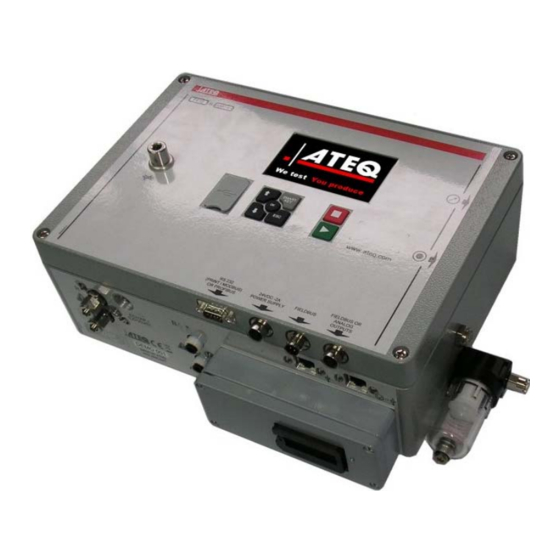
Sign In
Upload
Manuals
Brands
ATEQ Manuals
Cables and connectors
F610
ATEQ F610 Manuals
Manuals and User Guides for ATEQ F610. We have
3
ATEQ F610 manuals available for free PDF download: User Manual, Quick Start Manual
ATEQ F610 User Manual (215 pages)
Brand:
ATEQ
| Category:
Test Equipment
| Size: 3 MB
Table of Contents
Index
3
Functions Management
5
Menus Tree
7
Special Cycles Menu
7
Parameters Menu
8
Functions Menu
11
Available Functions for Leak Test
11
Available Functions for Blockage Test
15
Available Functions for Desensitized Test
17
Available Functions for Operator Test
20
Available Functions for Burst Test
21
Available Functions for Volume Test
23
Configuration Menu
25
Service Menu
29
Results Menu
30
Menus USB
30
Name Function
31
Program Sequencing Function
33
Associated Parameters to be Set
33
Chaining Conditions
33
Units Function
35
Select Cal-Pa or Cal-Pa/S
36
Special Cycles
37
Custom Unit Learning
37
Custome Unit Check
38
Custom Unit Check + Custom Unit Learn
38
Automatic Connectors Function
39
Calibration Check Function
40
Special Cycle
41
ATR 0 - 1 - 2 - 3 Functions
43
Atr0
43
Atr1
44
Atr 2
44
Atr3
45
Transient Drift
45
Pre-Fill Type
49
Ballistic
50
Fill Ramp
50
Pre-Fill Regulator
50
Full Type
51
Fill Regulator
51
Fill Adjust
51
Valves Codes/Auxiliary Outputs
53
Optional Valve Code Board
53
24V Auxiliary Outputs
55
End of Cycle
57
Relay Sequencing Related to Different End of Cycle
57
"Automatic Reset" Cycle End
58
Ending a Cycle with the Reset Key ("Automatic Reset" Cycle End)
59
"Reset + Dump" Cycle End (Automatic Dump)
60
"Fill" Cycle End
61
"Double Reset + Dump" Cycle End (Automatic Pump)
62
Mini Valve
64
Rework Limits
65
Sealed Components
67
Volume Fill
67
Part Transfer
67
Test Modes
68
Carrying out the Cycles and Settings
68
Learning Cycles
68
LE 3 Types of Sealed Components
70
Configuration
72
Sealed Components Special Cycle Learning
73
N Tests
75
Cycle Progress
75
Parametrage
76
Reference Volume
77
Presentation
77
Parametring
77
Stamping Function
78
Temperature Correction 1
79
Peak Hold
80
Sign
81
Filter
82
Run a Special Cycle
83
Special Cycles List
84
Flow Level Function
85
No Negative
86
Absolute
87
Display Mode
88
Dump off
89
Service Special Cycles
90
Activation
91
Starting the Service Special Cycles
92
Sensor Calibration
92
Piezzo Sensors
92
Differential Sensor
93
Valve Auto-Test
94
Date/Time
95
Storage (Save On)
96
Buzzer
97
Language
98
Electronic Regulator
99
Regulator Control
100
Permanent Regulator
102
Piezo Auto Zero
103
Auto Zero Short
105
Dump Level
107
Rs232
108
Printer Mode
109
Examples of Results Frames
110
Export Mode
113
Print Parameters
114
Security
116
I/O Configuration
118
Outputs Configuration
118
Inputs Configuration
120
External Dump
122
Synchro Test
123
Valve Service (Counters)
125
I/O
126
System Information
128
Reset Parameters
130
Definition, Characteristics and Measurement Principles
131
Measurement Characteristics
131
Pressure Drop Measurement/Test Pressure Measurement
131
Mechanical Pressure Regulation
131
The Different Tests
132
Leak Test
132
Direct or Pressure Drop Measurement
133
Indirect Pressure Rise Measurement
133
Sealed Component Measurement
133
Three Types of Leak Test
134
Test with Reference
134
Test Without Reference
134
Test with Central Zero
134
Direct Pressure Measurement
135
Blockage Test
136
Desensitized Test
136
Operator Test
136
Burst Test
137
Volume Test
137
Front Panel and Interfaces
138
Product View
138
Display
139
Cycle Keys
139
Navigation Keys
139
Quick Disconnect
140
Air Supply
141
Start-Up Setting
142
Powering up
142
Screen Detail
144
Creation of Test Program
145
Selection of the Test Type
145
Program Selection
147
Leak Program Parameters
148
Adjust Procedure
148
Parameters Definition
150
Coupling Time
150
Fill Time
150
Stabilization Time
150
Test Time
151
Dump Time
151
Pressure Units
151
Maximum Fill
151
Minimum Fill
152
Reject Unit
152
Reference Fail
152
Programs Management
153
Copy-Paste a Program
153
Program Deletion or Program Name Delection
155
Available Functions
156
Test Cycle Management
157
Starting a Cycle
157
Test Pressure Adjustment
157
Run a Measurement Cycle
157
Stopping a Cycle
158
Accessories
159
Power Supply Devices
159
Optional Accessories
160
Calibrated Master Leak
160
Filtration Kit
162
Needle Valve and Leak/Flow Calibrator
162
CDF (Leak/Flow Calibration)
163
Need Valve
163
3/2 Valve (Y-Valve)
163
Quick Connectors with Expandable Joints
164
Remote Controls
165
Reset/Start Remote
165
Four-Function 128 Programs Remote Control
165
Error Messages
166
Measurements Errors
167
ATF Function
169
"Cut Off" Function
170
Displaying Results in Flow Unit
171
"Smart Key"
174
Usb
177
By Pass
178
Electric Connectors
179
Front Face Connectors
179
USB Connector
179
Lower Side Connectors
179
Supply the Device with 24 V DC
180
RS232 Connector Printer/Modbus or Profibus
180
Devicenet, Profinet or Ethernet Connectors
181
Connector in Profibus Mode
181
Devicenet Input/Output
181
Input and Output Profinet
181
Analog Outputs
182
Connector Codes 6 Output / 6 Inputs
182
Input and Output Ethernet/Ip
182
Connector I/O All or Nothing
183
Connector (I/O Inputs/Outputs) Graphical Representation
183
PLC in NPN Mode Connection
183
PLC in PNP Mode Connection
184
Lights Connection
184
Program Selection Extension Connector
185
Combinations of Pins to Activate to Select Programs
185
Rear Side Connectors
186
USB Connector (Front Face)
186
RS232 Connector Printer/Mobdus Profibus
188
Connector in RS232 Mode
188
Connector Devicenet Input or Analog Outputs
189
Devicenet Input
189
J2 Devicenet Output
189
Connection for Analog Outputs
189
J3 Connector (I/O Inputs/Outputs) Graphical Representation
190
Connector Codes 6 Output/6 Inputs
193
Rear Face USB
193
Electric Connectors (F670)
194
Power Supply with 100/240V AC and On/Off Switch
195
J1 RS232 Connector Printer
195
Devicenet, Profinet or Ethernet Connectors
196
J7 Connector I/O All or Nothing
197
J6 Connector
200
Pneumatic Connectors
201
Pneumatic Test Outputs
201
Automatic Connector a and B
201
Quick Connectors
201
Pneumatic Supply
202
Pressure Unit
203
USB (Automatism)
204
Can Status
209
Burst Test Parameters
211
Advertisement
ATEQ F610 Quick Start Manual (28 pages)
Brand:
ATEQ
| Category:
Test Equipment
| Size: 0 MB
Table of Contents
Table of Contents
3
Preambule
4
Definition of the Ateq F610
4
Measurement Characteristics
4
The Main Types of Measurement
5
The Three Types of Test
5
Measurement Cycle
5
Installation
6
Appearance of the Ateq F610
6
Electrics Connectors
7
Pneumatic Supply
11
Pneumatic Connectors
12
User Interfaces
13
Cycle Keys
13
Touches de Navigation
13
Starting up and Adjustments
15
Test Menu
15
Main Menu
15
Lock Parameters
15
Programs Management
16
Parameters
17
Start and Stop Measurement Cycle
18
Functions
19
Others Menus
20
Special Cycles
20
Menu Configuration
21
Service Menu Maintenance
22
Results Menu
22
Usb Menu
22
Accessories and Characteristics
23
Accessories Provided
23
Accessories in Option
23
Technical Characteristic of the F610
24
Errors and Faults
25
Error Messages
25
In Case of Operation Doubt
25
Index
26
ATEQ F610 User Manual (8 pages)
Electric connectors
Brand:
ATEQ
| Category:
Cables and connectors
| Size: 0 MB
Table of Contents
1. Front Face Connectors
1
1.1. Usb Connector
1
2. Lower Side Connectors
1
Electric Connectors
2
3.1. Supply the Device with 24 V DC
2
3.1.1. Supply the Device with 24 V DC - 2A on the M12 Connector
2
3.1.2. Supply the Device with 24 V DC - 2A on the Relay Board
2
3.2. Rs232 Connector Printer / Modbus or Profibus
2
3.2.1. Connector in RS232 Mode
2
3.2.1. 1) Examples of RS232 Cables
2
3.2.2. Connector in Profibus Mode
3
3.3. Devicenet, Profinet or Ethernet Connectors (Option)
3
3.3.1. Devicenet Input (Option)
3
3.3.2. J2 Devicenet Output (Option)
3
3.3.3. Wiring Devicenet
3
3.3.4. Input and Output Profinet
3
3.3.5. Input and Output Ethernet/Ip
4
3.4. Analog Outputs (Option)
4
4. Others Connectors
4
4.1. Connector Codes 6 Output / 6 Inputs (Option)
4
4.2. Connector I/O All or Nothing
5
4.2.1. Connector (I/O Inputs/Outputs) Graphical Representation
5
4.2.1. 1) PLC in NPN Mode Connection
5
4.2.1. 2) PLC in PNP Mode Connection
6
4.2.1. 3) Lights Connection
6
4.3. Program Selection Extension Connector (Option)
7
Advertisement
Advertisement
Related Products
ATEQ F620
ATEQ F670
ATEQ F6 Profinet Series
ATEQ F6Class
ATEQ F600
ATEQ F600HP
ATEQ F580
ATEQ F20A
ATEQ F5800
ATEQ F5200
ATEQ Categories
Test Equipment
Measuring Instruments
Security Sensors
Diagnostic Equipment
GPS
More ATEQ Manuals
Login
Sign In
OR
Sign in with Facebook
Sign in with Google
Upload manual
Upload from disk
Upload from URL