Sign In
Upload
Manuals
Brands
Artesyn Manuals
Control Unit
MVME7616E Series
Artesyn MVME7616E Series Manuals
Manuals and User Guides for Artesyn MVME7616E Series. We have
1
Artesyn MVME7616E Series manual available for free PDF download: Installation And Use Manual
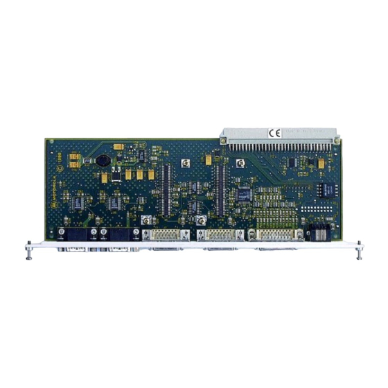
Artesyn MVME7616E Series Installation And Use Manual (56 pages)
Transition Module
Brand:
Artesyn
| Category:
Control Unit
| Size: 0 MB
Table of Contents
Table of Contents
3
About this Manual
9
1 General Information
13
Overview
13
Features
13
General Description
13
Figure 1-1 RTM Front Panel and Components Side
14
Serial Port Interface Modules
15
P2 Adapter Boards
15
Three-Row P2 Adapter (MVME761-001)
16
Figure 1-2 Three Row P2 Adapter
16
Five-Row P2 Adapter (MVME761-011)
17
Connectors and Cables
17
Five Row P2 Adapter
17
Table 1-2 MVME761 Transition Module Connectors
18
Table 1-3 3-Row P2 Adapter Connectors (MVME761-001)
18
Table 1-4 5-Row P2 Adapter Connectors (MVME761-011)
18
Specifications
19
Table 1-5 Transition Module Cables
19
Table 1-6 MVME761-0X1 Specifications
19
1.10 Cooling Requirements
20
1.11 FCC Compliance
20
2 Hardware Preparation and Installation
21
Overview
21
Unpacking the Hardware
21
Installing the Serial Interface Modules
21
Figure 2-1 Serial Port Interface Jumper Setting
21
Figure 2-2 SIM Configuration
22
Installing the SIM
23
Installing the Transition Module and P2 Adapter
24
Figure 2-4 Chassis Connections
25
3 Functional Description
27
Overview
27
Circuitry
27
Figure 3-1 Transition Module Block Diagram
28
P2 Signal Multiplexing (P2MX)
29
Figure 3-2 3-Row DIN Backplane P2 Adapter Block Diagram
29
Figure 3-3 5-Row DIN Backplane P2 Adapter Block Diagram
29
Table 3-1 P2 Signal Multiplexing Sequence
31
Serial Interface Module Circuitry
32
Figure 3-4 Multiplex Signal Timing Chart
32
COM1 and COM2 Asynchronous Serial Ports
34
Figure 3-5 EIA-574 DTE Port Configuration
35
Asynchronous/Synchronous Serial Ports
36
Figure 3-6 EIA232-DCE Configuration Port 3
37
Figure
38
Figure 3-7 EIA232-DCE Configuration Port 4
38
Figure 3-8 EIA232-DTE Configuration Port 3
39
Figure 3-9 EIA232-DTE Configuration Port 4
40
4 Connector Pin Assignments
41
Overview
41
P2 Connector
41
Table 4-1 P2 Connector Pin Assignments
41
Asynchronous Serial Port Connectors (J5/J6)
43
Asynchronous/Synchronous Serial Port Connectors (J7/J8)
43
Table 4-2 COM1 and COM2 Pin Assignments
43
Table 4-3 Serial Port 3 Pin Assignments
43
Table 4-4 Serial Port 4 Pin Assignments
44
Parallel I/O Port Connector (J4)
45
Table 4-5 Parallel I/O Connector Pin Assignments
45
Ethernet Connector (J9)
46
P2 Adapter Connectors
46
3-Row P2 Adapter (J2)
46
Table 4-6 10Base-T/100Base-TX Pin Assignments
46
Table 4-7 8-Bit SCSI Connector (3-Row P2 Adapter)
46
3-Row P2 Adapter (J3)
48
Table 4-8 VME Connector (3-Row P2 Adapter)
48
5-Row P2 Adapter (J1)
49
Table 4-9 16-Bit SCSI Connector (5-Row P2 Adapter)
49
PMC I/O, 5-Row P2 Adapter (J3)
51
Table 4-10 PMC I/O Connector (5-Row P2 Adapter)
51
5-Row P2 Adapter (J4)
52
Table 4-11 VME Connector (3-Row P2 Adapter)
52
Advertisement
Advertisement
Related Products
Artesyn MVME721X RTM
Artesyn MVME7616E-001
Artesyn MVME7616E-011
Artesyn MVME7100
Artesyn MVME2502
Artesyn MVME5100
Artesyn MVME8105
Artesyn MVME2500-01080101E
Artesyn MVME2500-021CC
Artesyn MVME5500
Artesyn Categories
Motherboard
Server
Single board computers
PCI Card
Control Unit
More Artesyn Manuals
Login
Sign In
OR
Sign in with Facebook
Sign in with Google
Upload manual
Upload from disk
Upload from URL