Sign In
Upload
Manuals
Brands
Anritsu Manuals
Tablet
MU100010A Network Master Pro
Anritsu MU100010A Network Master Pro Manuals
Manuals and User Guides for Anritsu MU100010A Network Master Pro. We have
6
Anritsu MU100010A Network Master Pro manuals available for free PDF download: Operation Manual, Manual, Configuration Manual, Quick Reference Manual
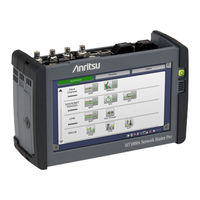
Anritsu MU100010A Network Master Pro Operation Manual (449 pages)
Brand:
Anritsu
| Category:
Test Equipment
| Size: 17 MB
Table of Contents
Table of Contents
4
1 Introduction
15
Mainframe
16
Multirate Module (MU100010A)
17
Symbols and Conventions
18
Symbols Used in Manual
18
Safety Symbols Used on Equipment
18
Notes
18
Hints
18
Warnings
20
Cautions
22
Cautions against Computer Virus Infection
23
Precautions
24
ESD (Electrostatic Discharge)
24
Optical Surfaces
24
Cautions on Handling Optical Fiber Cables
24
Ventilation
26
Countries and Regions Permitting WLAN Use
26
2 Configuration
27
Delivered Accessories
28
Standard Accessories
28
Optional Accessories
28
Mains Power Adapter
29
Connecting Mains Power Adapter
29
Rechargeable Battery
30
Installing or Replacing Battery
30
Charging Battery in Fast Mode
31
Charging Battery in Normal Mode
31
Battery Status Information
31
Measurement Cables
32
Connecting Measurement Cables
32
Support Stand and Carrying Strap
33
Support Stand
33
Carrying Strap and Handle
33
3 Man-Machine-Interface
37
Touch Screen Display
38
Key Operation
39
Power Button
39
Head Set
41
Connector Panel
42
Test Interfaces
42
Service Interfaces
43
Remote Operation
44
Installation of Control Software
44
Connection and Setup
44
Communication Ports
45
Starting Control Software
45
Remote Upgrade
46
Remote Wake up
47
Remote Reset
47
Stand-Alone Editor
48
Command-Based Remote Control
49
File Access Via USB Interface
49
File Access Via Ethernet Interface
50
Accessing Files in Network Master from the PC
50
Mounting the Shared Folder of Networked PC to the Network Master
50
External GPS Receiver
52
Remote Control Via GPIB
53
4 Graphical User Interface
55
General Handling of the GUI
56
GUI Concept
56
Navigating in the GUI
56
Layout of the GUI Screens
58
Starting the Application
59
Switching the Applications
62
Operating the Application
62
Lamp Indication of Alarm/Error Status
64
Test Status Summary
65
Keypads for Entering Text in Fields
66
User Pattern Editor
67
Prompts to Confirm Dependencies
67
Toolbars
68
Instrument Toolbar
68
Application Toolbar
78
Startup and Switch-Off Sequences
84
Instrument Startup
84
Application Startup
84
Accessing Previous Tests and Test Results
84
Closing an Application
85
Switching off the Instrument
85
5 Sdh/Sonet/Pdh/Dsn Applications
87
SDH Setup and Status
88
Transmitter Setup
88
Physical Setup
88
SDH Frame Setup
89
Receiver Setup
93
Physical Setup
93
SDH Frame Setup
93
Status Information
94
Status Summary
94
Physical Details
95
Alarms and Errors
96
OH Capture
97
Tributary Scan
98
Transceiver
99
Errors/Alarms Insertion
99
SDH Alarms/Errors
100
SDH Frequency
101
SDH Pointer
101
SONET Setup and Status
102
Transmitter Setup
102
Physical Setup
102
SONET Frame Setup
103
Receiver Setup
107
Physical Setup
107
SONET Frame Setup
107
Status Information
108
Status Summary
108
Physical Details
109
Alarms and Errors
109
OH Capture
110
Tributary Scan
110
Transceiver
110
Errors/Alarms Insertion
110
E1 Setup and Status
111
Transmitter Setup
111
Physical Setup
111
E1 Signal Setup
112
Receiver Setup
116
Physical Setup
116
E1 Signal Setup
118
Status Information
120
Status Summary
120
Physical Details
121
Alarms and Errors
121
Alignment
122
Cas
123
Audio
124
Traffic
125
Errors/Alarms Insertion
126
PDH Alarms/Errors
126
PDH Frequency
127
DS1/J1 Setup and Status
128
Transmitter Setup
128
Physical Setup
128
DS1/J1 Signal Setup
129
Receiver Setup
133
Physical Setup
133
DS1/J1 Signal Setup
133
Status Information
135
Status Summary
135
Physical Details
136
Alarms and Errors
136
Alignment
137
Cas
137
Audio
138
Traffic
138
Errors/Alarms Insertion
138
E3 Setup and Status
139
Transmitter Setup
139
Physical Setup
139
E3 Signal Setup
140
Receiver Setup
141
Physical Setup
141
E3 Signal Setup
141
Status Information
142
Status Summary
142
Physical Details
143
Alarms and Errors
143
Errors/Alarms Insertion
143
DS3 Setup and Status
144
Transmitter Setup
144
Physical Setup
144
DS3 Signal Setup
145
Receiver Setup
147
Physical Setup
147
DS3 Signal Setup
148
Status Information
149
Status Summary
149
Physical Details
149
Alarms and Errors
149
Alignment
150
Errors/Alarms Insertion
151
E4 Setup and Status
152
Transmitter Setup
152
Physical Setup
152
E4 Signal Setup
153
Receiver Setup
153
Physical Setup
153
E4 Signal Setup
154
Status Information
155
Status Summary
155
Physical Details
155
Alarms and Errors
155
Errors/Alarms Insertion
156
Aps
157
Ports Setup and Status
157
Test Setup
157
Threshold
157
Test Results
158
Summary
158
Details for APS
158
Protocol Interpretation
159
Event Log
160
Statistics
160
Bert
161
Ports Setup and Status
161
Test Setup
161
Control
161
Thresholds
163
Test Results
164
Summary
164
Pointer Movement
165
Event Log
166
Statistics
167
Rtd
172
Ports Setup and Status
172
Test Setup
172
Control
172
Threshold
173
Test Results
173
Summary
173
Detailed
173
Event Log
174
Statistics
174
6 Ethernet Applications
175
Ethernet Setup and Status
176
Physical Port Setup
176
Port Configuration Parameters
176
Port Setup (Detailed Mode)
177
Ethernet Frame Setup
179
Wan
179
Stream
179
Swap
199
Settings
199
Synce
201
IEEE 1588V2
202
Oam
207
Filter
218
Status Information
220
Status Summary
220
Physical Details
221
Interface
222
OH Capture
223
Synce
223
IEEE 1588V2
224
Oam
226
Frame Capture
228
Transceiver
230
Errors/Alarms Insertion
231
Ethernet LAN
231
Ethernet PCS Alarms/Errors
232
Ethernet WAN
233
Ethernet Frequency
233
Bert
234
Ports Setup and Status
234
Test Setup
234
Control
234
Generator
236
Stream
237
Thresholds
239
Test Results
240
Summary
240
Ieee1588V2 Log
242
OAM Log
243
Event Log
243
Statistics
243
Cable
248
Test Setup
248
Channel Statistics
250
Ports Setup and Status
250
Test Setup
250
Control
250
Generator
250
Stream
250
Definitions
250
Test Results
251
Summary
251
Ieee1588V2 Log
252
Event Log
252
Statistics
252
Mon/Gen
253
Ports Setup and Status
253
Test Setup
253
Control
253
Generator
253
Streams
253
Thresholds
254
Test Results
254
Summary
254
Ieee1588V2 Log
256
OAM Log
256
Event Log
256
Statistics
257
Pass through
260
Ports Setup and Status
260
Test Setup
260
Control
260
Thresholds
260
Test Results
261
Summary
261
Event Log
261
Statistics
261
Ping
262
Ports Setup and Status
262
Test Setup
262
Test Results
263
Summary
263
Ieee1588V2 Log
263
Detailed
263
Event Log
264
Statistics
264
Reflector
265
Ports Setup and Status
265
Test Setup
266
Control
266
Thresholds
266
Test Results
267
Summary
267
Event Log
267
Statistics
267
Rfc 2544
268
Ports Setup and Status
268
Test Setup
268
Control
268
Throughput
271
Frame Loss
273
Throughput and Frame Loss
273
Latency
274
Burst
275
Advanced
276
Test Results
277
Summary
278
Throughput
278
Frame Loss
279
Throughput and Frame Loss
280
Latency
280
Burst
281
Event Log
281
Statistics
281
Throughput Calculation
281
Rfc 6349
283
Ports Setup and Status
283
Test Setup
283
Control
283
Mtu / Rtt
285
Windows Scan / Throughput
285
Multi-Service
287
Test Results
287
Summary
288
RFC6349 Metrics
288
Window Scan
289
Throughput
289
Multi-Service
290
Event Log
291
Statistics
291
Sat 1564
292
Ports Setup and Status
292
Test Setup
292
Control
292
Services
295
Advanced
300
Test Results
300
Summary
301
Configuration Test
301
Performance Test
302
Event Log
303
Statistics
303
Ports Setup and Status
304
Test Setup
304
Test Results
305
Summary
305
Ieee1588V2 Log
305
Event Log
306
Statistics
306
7 OTN Applications
307
OTN Setup and Status
308
Transmitter Setup
308
Physical Setup
308
Otuk Frame Setup
309
Mapping
310
Overhead
312
Tp/Ts
319
Gfp-T
319
Gfp-F
319
Receiver Setup
320
Physical Setup
320
Otuk Frame Setup
321
Tp/Ts
322
TTI Detection
323
MSIM Detection
323
Status Information
324
Status Summary
324
Physical Details
324
Alarms and Errors
325
OH Capture
327
Tributary Scan
328
Transceiver
329
Error/Alarm Insertion
330
Otn
330
OTN Frequency
332
OTN Justification
332
Aps
333
Ports Setup and Status
333
Advertisement
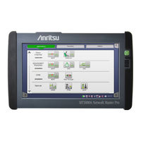
Anritsu MU100010A Network Master Pro Operation Manual (545 pages)
Network Master Pro
Brand:
Anritsu
| Category:
Measuring Instruments
| Size: 22 MB
Table of Contents
Table of Contents
4
Introduction Introduction 11
12
Symbols Used in Manual
14
Option
15
Dangers
16
Cautions
18
Cautions against Computer Virus Infection
19
Installation
20
Optical Surfaces
21
Caution When Handling MU100090A
23
Configuration Configuration 25
26
Connecting Mains Power Adapter
28
Installing or Replacing Battery
29
Charging Battery in Fast Mode
30
Connecting Measurement Cables
31
Support Stand
32
Replacing the MU100010A 10G Multirate Modules
37
Attaching the MU100090A and MU100010A
38
Power Button
43
Test Interfaces
46
GPS Disciplined Oscillator Interfaces
48
Installation of Control Software
50
Communication Ports
51
Starting Control Software
52
Remote Upgrade
53
Remote Wake up
54
Accessing Files in Network Master from the PC
58
G0325A GPS Receiver
60
Operating GPS Receiver
61
GUI Concept
64
Navigating in the GUI
65
Layout of the GUI Screens
66
Lamp Indication of Alarm/Error Status
73
Keypads for Entering Text in Fields
75
User Pattern Editor
76
Instrument Toolbar
77
Application Toolbar
88
Instrument Startup
94
Accessing Previous Tests and Test Results
95
Switching off the Instrument
96
Transmitter Setup
98
Receiver Setup
103
Status Information
105
Errors/Alarms Insertion
111
Transmitter Setup
113
Receiver Setup
118
Status Information
120
Errors/Alarms Insertion
122
Transmitter Setup
123
Receiver Setup
129
Status Information
134
Errors/Alarms Insertion
140
Transmitter Setup
142
Receiver Setup
147
Status Information
150
Errors/Alarms Insertion
153
Transmitter Setup
154
Receiver Setup
156
Status Information
158
Errors/Alarms Insertion
159
Transmitter Setup
160
Receiver Setup
164
Status Information
166
Errors/Alarms Insertion
169
Transmitter Setup
170
Receiver Setup
172
Status Information
173
Errors/Alarms Insertion
174
Ports Setup and Status
175
Test Results
176
Ports Setup and Status
180
Test Results
185
Ports Setup and Status
196
Test Results
197
Physical Port Setup
200
Ethernet Frame Setup
203
Status Information
253
Errors/Alarms Insertion
265
Ports Setup and Status
269
Test Results
280
Test Setup
290
Ports Setup and Status
292
Test Results
293
Ports Setup and Status
296
Test Results
301
Ports Setup and Status
306
Test Results
307
Ports Setup and Status
309
Test Results
310
Ports Setup and Status
312
Test Setup
313
Test Results
314
Ports Setup and Status
315
Test Results
326
Throughput Calculation
331
Ports Setup and Status
333
Test Results
338
Ports Setup and Status
343
Test Results
352
Ports Setup and Status
356
Test Results
357
Ports Setup and Status
361
Test Results
364
Transmitter Setup
372
Receiver Setup
386
Status Information
391
Error/Alarm Insertion
397
Ports Setup and Status
401
Test Results
402
Ports Setup and Status
405
Test Results
409
Ports Setup and Status
414
Test Results
415
Physical Port Setup
419
CPRI/OBSAI Frame Setup
420
Status Information
421
Error/Alarm Insertion
424
Ports Setup and Status
426
Test Results
429
Ports Setup and Status
433
Physical Port Setup
437
Status Information
440
Errors/Alarms Insertion
442
Ports Setup and Status
444
Test Results
449
Ports Setup and Status
454
Test Results
455
Scenario Manager
460
Running the Scenario
462
Test Setup
464
Application Toolbar
468
Test Setup
469
Test Results
470
Configuration
474
External Interfaces
475
Environment Performance
476
Configuration
477
External Interfaces
478
Environment Performance
481
Mechanical Performance
482
Configuration
483
GPS Synchronization
484
Ethernet Measurements
485
Sdh/Sonet/Pdh/Dsn
497
Fibre Channel
512
Cpri/Obsai
513
Support 12 Support 517
517
Maintenance
518
Installation by Using USB Memory Stick
522
Before You Obtain Assistance
523
Repackaging
524
Equipment Certificate
525
Anritsu Corporation Contact
526
Product Model
533
Authorized Representative
534
CE Declaration
535
Product Model
536
Laser Safety Classifications
537
Indication Labels on Product
538
Laser Radiation Markings
539
Japan MIC
540
Europe CE
541
China SRRC
542
Mexico IFETEL
543
Notes on Export Management
544
Information for the Chinese Market Only
545
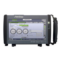
Anritsu MU100010A Network Master Pro Manual (36 pages)
Brand:
Anritsu
| Category:
Measuring Instruments
| Size: 3 MB
Table of Contents
Table of Contents
2
Network Master Pro MT1040A Main Frame
3
New Purchase Flowchart
4
New Purchase
6
Transport Module
6
400G (QSFP-DD) Multirate Module MU104014A
6
Selecting Protocol Options
6
400G (OSFP) Multirate Module MU104015A
7
Selecting Protocol Options
7
100G Multirate Module MU104011A
8
Selecting Protocol Options
8
Multirate Module MU100010A
9
Selecting Protocol Options
9
100G Multirate Module MU100011A
10
Selecting Protocol Options
10
Selecting Optical Transceiver for Transport Module
11
Selecting Transport Test Option
12
OTDR Module
13
OTDR Module 1310/1550 Nm SMF MU100020A
13
Selecting Dynamic Range
13
Selecting Polish Type/Connector Adapter
13
Selecting Visible Light Source Option
13
OTDR Module 1310/1550/850/1300 Nm SMF/MMF MU100021A
14
Selecting Dynamic Range
14
Selecting Polish Type/Connector Adapter
14
Selecting Visible Light Source Option
14
OTDR Module 1310/1550/1625 Nm SMF MU100022A
15
Selecting Dynamic Range
15
Selecting Polish Type/Connector Adapter
15
Selecting Visible Light Source Option
15
OTDR Module 1310/1550 Nm, 1650 Nm SMF MU100023A
16
Selecting Dynamic Range
16
Selecting Polish Type/Connector Adapter
16
Selecting Visible Light Source Option
16
Selecting MU100020A/MU100021A/MU100022A/MU100023A Options
17
OTDR Module Conversion Connector Adapters
17
Optical Fiber Conversion Adapters
17
Others
17
Common Application Parts, Extended Warranty Services and Remote Software Service
18
MT1040A Power Supply Option
18
MT1040A Selecting Common Application Parts
18
MT1040A Selecting Extended Warranty Services
20
Remote Software Service
21
Additional Purchases Flowchart
22
Additional Purchases
24
Adding New Options to Previously Purchased MT1040A
24
Adding Test Protocols for Transport Module
24
Adding Main Frame Options for Transport Function
29
Adding Transport Module
29
Adding OTDR Module
29
Adding MX109020A Option
29
Configuration Examples
30
Order Sheet
31
Method for Adding Measurement Modules
32
Advertisement
Anritsu MU100010A Network Master Pro Configuration Manual (24 pages)
Network Master Series 10G Multirate Module,OTDR Module,CPRI RF Module,High Performance GPS Disciplined Oscillator
Brand:
Anritsu
| Category:
Measuring Instruments
| Size: 3 MB
Table of Contents
Table of Contents
2
Network Master Pro MT1000A Main Frame
3
New Purchase Flowchart
4
New Purchase
6
Transport Function
6
Multirate Module MU100010A
6
Selecting Protocol Options
6
Selecting Optical Transceiver (for Transport Module)
7
Choosing High-Accuracy Oscillator Option
8
Selecting Transport Test Option
8
Optical Function
9
OTDR Module 1310/1550 Nm SMF MU100020A
9
Selecting Dynamic Range
9
Selecting Polish Type/Connector Adapter
9
Selecting Visible Light Source Option
9
OTDR Module 1310/1550/850/1300 Nm SMF/MMF MU100021A
10
Selecting Dynamic Range
10
Selecting Polish Type/Connector Adapter
10
Selecting Visible Light Source Option
10
OTDR Module 1310/1550/1625 Nm SMF MU100022A
11
Selecting Dynamic Range
11
Selecting Polish Type/Connector Adapter
11
Selecting Visible Light Source Option
11
Selecting MU100020A/MU100021A/MU100022A Options
12
OTDR Module Conversion Connector Adapters
12
Optical Fiber Conversion Adapters
12
Others
12
CPRI RF IQ Data Measurement
13
CPRI RF Module MU100040A
13
Selecting Module Options
13
Selecting MU100040A Options
13
Common Application Parts and Extended Warranty Services
14
MT1000A Selecting Common Application Parts
14
MT1000A Selecting Extended Warranty Services
15
Additional Purchases Flowchart
16
Additional Purchases
18
Adding New Options to Previously Purchased MT1000A
18
Adding Test Protocols for Transport Module
18
Adding Main Frame Options for Transport Function
19
Adding Transport Module
19
Adding High-Accuracy Oscillator for Transport Function
19
Adding OTDR Module
19
Adding CPRI RF Module
19
Configuration Examples
20
Procedure for Attaching some Measurement Modules
22
Order Sheet
24
Anritsu MU100010A Network Master Pro Configuration Manual (9 pages)
Network Master Series
Brand:
Anritsu
| Category:
Tablet
| Size: 0 MB
Table of Contents
1. MT1000A Network Master Pro Hardware Options (Required)
2
2. Protocol Options (Requires One at Minimum)
2
Example Configurations
3
4. Other Options (Not Mandatory)
4
5. Accessory Parts - Optical Transceivers (for Optical Transmission)
4
Retrofit Options
5
6. Other Accessory Options (Not Mandatory)
5
8. Recommended Item Number Sequence in Purchase Orders
6
Note
7
Anritsu MU100010A Network Master Pro Quick Reference Manual (4 pages)
Brand:
Anritsu
| Category:
Test Equipment
| Size: 0 MB
Advertisement
Related Products
Anritsu MT1000A Network Master Pro
Anritsu Network Master Pro MU100011A
Anritsu MU100040A
Anritsu MU100040B
Anritsu MU100020A
Anritsu MU100022A
Anritsu MU100021A
Anritsu Network Master Pro MU100023A
Anritsu MU100090B001
Anritsu MU100090B002
Anritsu Categories
Measuring Instruments
Test Equipment
Portable Generator
Control Unit
Thermometer
More Anritsu Manuals
Login
Sign In
OR
Sign in with Facebook
Sign in with Google
Upload manual
Upload from disk
Upload from URL