Sign In
Upload
Manuals
Brands
Allen-Bradley Manuals
Controller
SMC-50
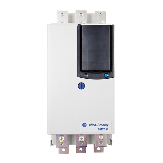
Allen-Bradley SMC-50 Manuals
Manuals and User Guides for Allen-Bradley SMC-50. We have
2
Allen-Bradley SMC-50 manuals available for free PDF download: User Manual, Quick Start Manual
Allen-Bradley SMC-50 User Manual (292 pages)
CENTERLINE Medium Voltage Motor Controller
Brand:
Allen-Bradley
| Category:
Controller
| Size: 17.63 MB
Table of Contents
Table of Contents
3
Additional Resources
11
Manual Objectives
11
Preface
11
Service Procedure
11
Chapter 1 Overview
13
1503E - OEM Controller
13
1560F - Retrofit Controller
13
Product Overview
13
1562F - Combination Controller
14
SMC-50™ Control Module
14
Starting Modes
15
Soft Start
15
Sensorless Linear Speed Acceleration
16
Torque Control Start
17
Current Limit Start
17
Selectable Kickstart
18
Pump Control Mode
18
Dual Ramp Start
20
Emergency Bypass Run (Full Voltage Start)
20
Stopping Modes
21
Coast
21
Soft Stop
21
Linear Speed Deceleration
22
Pump Stop
23
Motor and Starter Protection Features
24
Overload Protection
25
Underload Protection
27
Undervoltage Protection
27
Overvoltage Protection
27
Voltage Unbalance Protection
28
Current Imbalance
28
Stall Protection and Jam Detection
28
Ground Fault
29
Thermistor/Ptc Protection
30
Open Gate
31
Line Faults with Phase Indication
31
Excessive Starts/Hour
32
Overtemperature
32
Overcurrent Protection
32
Total Harmonic Distortion (THD) Fault and Alarm
32
Metering
33
Metering System
33
Inputs and Outputs
34
Communication Interface
35
Programming
36
Status Indication
37
Hardware Description
38
Power Module
38
Current Loop Gate Driver (CLGD) Board
38
Interface Board
39
Functional Description
42
Bulletin 1562F • Standard Control
42
Bulletin 1562F • Programming Interface Control
43
Bulletin 1560F • Standard Control
44
Bulletin 1560F • Programming Interface Control
44
Chapter 2 Receiving
49
Installation
49
Safety and Codes
49
General Precautions
50
Transportation and Handling
50
Unpacking and Inspection
50
Installation Site
51
Mounting
52
Grounding Practices
52
Power Connections
53
Bulletin 1562F
53
Bulletin 1560F
54
Bulletin 1503E
60
Recommended Torque Values
53
Interlocking
60
Line and Load Power Wiring
60
Installation
61
Physical Location
61
Ground Bus Bar
61
Power and Control Wiring
61
Control Cables
61
Fiber-Optic Cables
62
Power Factor Correction Capacitors
62
Surge Arrestor Protection Devices
63
Motor Overload Protection
64
Two-Speed Motors
64
Multi-Motor Protection
64
EMC Compliance
65
Enclosure
65
Wiring
65
Control Power
66
Control Voltage
66
Control Wiring
66
Control Terminal Designations
66
Standard Control Terminal Block
66
Control Wiring Specifications
66
Rockwell Automation Publication 1560F-UM001A-EN-P - June
67
Chapter 3 Preliminary Setup
69
Commissioning Procedure
69
System Characteristics
69
Important Commissioning Checks
70
Preliminary Check
71
Hi-Pot and Insulation Resistance Test
72
Programming
72
SMC-50 Module
72
Motor Tuning
73
Power Supply Tests
77
Control Function Tests
80
Resistance Checks
80
Voltage Sensing Module
81
Start-Up
82
20-Him-C6S)
83
Password Modification Using the HIM
85
Parameter Access Level Modification Using the HIM
86
Chapter 4 Overview
83
Human Interface Module (HIM)
83
Programming
83
Parameter Management
87
RAM (Random Access Memory)
88
ROM (Read-Only Memory)-Set Defaults
88
Eeprom
89
Parameter Configuration
89
Using the START up Configuration Tool
89
20-Him-C6S)
89
Parameter Search and Configuration
93
Parameter Search and Configuration by Parameter
93
Number
93
Parameter Search and Configuration by File-Group
94
Structure
94
Parameter Configuration - Using the Setup File Group
96
Overview
96
Soft Start and Stop
97
Current Limit Start with Simple Stop Mode
99
Linear Acceleration (Linear Speed) Start with Stop
100
Torque Start with Stop
101
Pump Start with Stop
102
Full Voltage Start with Stop
104
Dual Ramp Start with Stop
105
Motor Protection
106
Parameter File-Group Structure
109
Option Module Configuration
112
Basic Configuration Using the HIM
112
150-SM4 Digital I/O Option Module
114
150-SM2 PTC, Ground Fault, and External Current
117
Transformer Module
117
Chapter 5 Overview
121
Metering
121
Viewing Metering Data
121
Resetting Metering Parameters
122
Metering Parameters
122
Current
122
Voltage
123
Torque
123
Power
124
Power Factor
125
Elapsed Time
125
Running Time
126
Motor Speed
126
Actual Start Time
126
Peak Start Current
127
Total Starts
127
Total Harmonic Distortion (THD)
127
Line Frequency
128
Current Imbalance
128
Voltage Unbalance
129
Chapter 6 Overview
131
HIM Control Buttons
131
HIM Control Screen
132
Copycat Function of the 20-HIM-A6
133
Optional HIM Operation
131
Chapter 7 Overview
135
Communication Ports
135
Communications
135
HIM Keypad and Displays
136
Connecting the HIM to the Control Module
136
Control Enable
137
Logic Mask Enable/Disable Using a HIM
137
Default Input/Output Communication Configuration
139
Variable Input/Output Configuration
139
Loss of Communication with DPI Device
139
Control Module-Bit Identification
140
SMC-50 Control Module—Bit Identification
140
Parameter Information
141
Reference/Feedback
141
Scale Factors for PLC Communication
141
Configuring Datalink
142
Criteria for Using Datalink
142
Rockwell Automation Publication 1560F-UM001A-EN-P - June
142
Display Text Unit Equivalents
142
Updating Firmware
143
Diagnostics
145
Protection Programming
145
Clear Fault
146
Fault Display (20-HIM-A6)
146
Fault and Alarm Buffer - Parameter List
147
Accessing the Fault and Alarm Parameters
147
Accessing the Fault and Alarm Buffers
148
Fault Codes
150
Auxiliary Relay Output Fault or Alarm Indication
155
Introduction
157
Chapter 8 Overview
145
Diagnostic Status Indicators
145
Troubleshooting
157
Control Module Removal
164
Real Time Clock (RTC) Battery Replacement
164
Voltage Feedback Circuit Tests
166
Voltage Sensing Board Replacement
167
Current Loop Power Supply
168
Circuit Board Replacement
169
Power Circuit Troubleshooting
170
Thyristor (SCR) Testing
170
SCR Replacement Procedure
171
Snubber and Resistor Circuit Testing
184
Snubber Resistor Replacement
186
Chapter 10 Preventive Maintenance Protection
191
Fault and Alarm
191
PM Starts Protection-Fault and Alarm
192
Maintenance
191
Safety and Preventative Maintenance
192
Periodic Inspection
193
Contamination
193
Vacuum Bottles
193
Terminals
194
Coils
194
Solid-State Devices
194
Static-Sensitive Items
194
Overload Maintenance after a Fault Condition
195
Final Check out
195
Keep Good Maintenance Records
195
Power Components
195
Control Components - Electronic
195
Interlocks
195
Barriers
196
Environmental Considerations
196
Hazardous Materials
196
Capacitor Dielectric Fluid
196
Printed Circuit Boards
197
Chromate Plating
197
In Case of Fire
197
Disposal
197
Parameter List
199
Appendix A Starting Duty
241
Appendix C
243
Bulletin 1562F • Standard Control
243
Bulletin 1562F • Programming Interface Control
244
Bulletin 1560F • Standard Control
245
Bulletin 1560F • Programming Interface Control
245
Functional Description
243
Appendix D Arcshield Design
251
Overview
251
Exhaust Systems: Chimney or Plenum Option
252
Plenum Information
252
Plenum Exhaust Considerations
253
Additional Notes
255
Chimney Exhaust Considerations
256
Chimney Information
256
Appendix E
257
Plenum Bracing
257
Recommended Torque Values
257
General Plenum Layout for Arcshield Line-Up
259
STEP 1 - Mounting a Single Plenum
260
Cabinet Preparation
260
Plenum Placement on Structure
261
Rockwell Automation Publication 1560F-UM001A-EN-P - June
262
STEP 4 – Closing the Front of the Plenum Sections
263
STEP 6 – Mounting Extension/Elbow to Plenum "Line-Up
264
STEP 7 – Additional Mounting Support
265
Recommended Torque Values
267
Appendix F General Plenum Layout for Arcshield Line-Up
268
Chimney Placement on Structure
269
Chapter 9 Introduction
271
Appendix G
272
Macro Blocks
272
Bit Inputs
273
Analog Inputs
274
Analog Outputs
275
Example 2: Wet Well Operation
277
Power Stacks
281
Accessories
285
Appendix H
287
Appendix I
287
Index
287
Advertisement
Allen-Bradley SMC-50 Quick Start Manual (40 pages)
smart motor controller
Brand:
Allen-Bradley
| Category:
Controller
| Size: 2.53 MB
Table of Contents
Important User Information
2
Table of Contents
3
About this Publication
5
Additional Resources
5
Preface
5
Terminology
5
General Precautions
6
Summary of Changes
7
Chapter 1 Enclosures
9
Installation
9
Mounting Requirements
10
Dimensions
11
Power Wiring
12
Power Lugs
13
Typical Power Diagrams
14
Control Wiring
15
Standard Control Terminal Block
15
Control Wiring Specifications
15
Typical Control Wiring Examples
17
Fan Wiring
19
Integrated Bypass Units
19
Solid-State Units
19
Upgraded Units
19
Option Modules
19
Bypass Operation and Diagrams
21
SMC-50 Controllers with Internal Bypass
21
SMC-50 Controllers with External Bypass
21
Chapter 2 Parameter Configuration
25
Parameter Configuration Using a 20-HIM-A6
25
Programming
25
Basic Parameter Access and Category/File Structure
26
Parameter Access
26
Category/File Structure
27
Quick Setup
29
Chapter 3 Operation
31
Motor Configuration
31
Motor Tuning
31
Operation and Troubleshooting
31
Resistive Load Control
32
Troubleshooting by Fault Code - Abbreviated Listing
33
Troubleshooting with Diagnostic Leds
33
Controller LED Status Indicator
33
Troubleshooting with Monitoring Equipment
33
SCCR Ratings
37
Advertisement
Related Products
Allen-Bradley SLC 500 Series
Allen-Bradley SLC 500
Allen-Bradley Stratix 2000
Allen-Bradley SLC 5/05 series
Allen-Bradley GuardShield Safe 2 PAC
Allen-Bradley GuardShield Safe 2
Allen-Bradley SafeZone maximum
ALLEN BRADLEY SLC 5/02
Allen Bradley SLC 500 DeviceNet
Allen-Bradley SLC 500 BASIC
Allen-Bradley Categories
Control Unit
Controller
I/O Systems
Power Supply
Switch
More Allen-Bradley Manuals
Login
Sign In
OR
Sign in with Facebook
Sign in with Google
Upload manual
Upload from disk
Upload from URL