Sign In
Upload
Manuals
Brands
Aerotech Manuals
Servo Drives
NDrive CP10
Aerotech NDrive CP10 Manuals
Manuals and User Guides for Aerotech NDrive CP10. We have
1
Aerotech NDrive CP10 manual available for free PDF download: User Manual
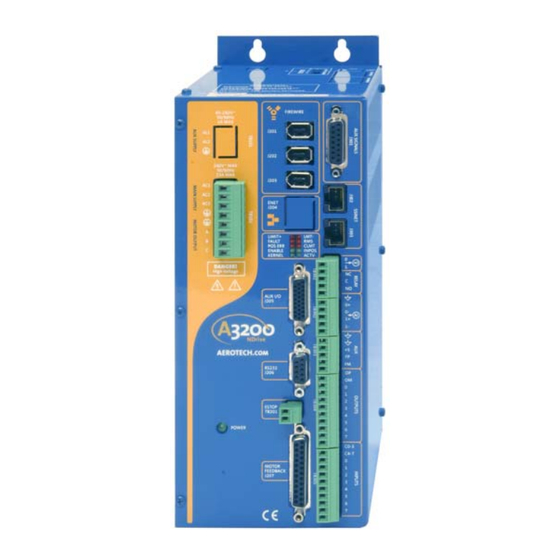
Aerotech NDrive CP10 User Manual (152 pages)
Digital Servo Drive
Brand:
Aerotech
| Category:
Servo Drives
| Size: 27 MB
Table of Contents
Revision History
3
Table of Contents
4
List of Figures
9
List of Tables
10
Declaration of Conformity
12
Regulatory Information
12
Chapter 1: Introduction
14
Figure 1-1. Ndrive HP 10/20/30 Networked Digital Drives
14
Feature Summary
15
Connection Overview
16
Figure 1-2. Ndrive HP Hardware
16
Functional Diagram
17
Figure 1-3. Functional Diagram
17
Ordering Information
18
Table 1-1. Models, Options, and Voltage Configurations
18
Table 1-2. Accessories
19
Specifications
20
Electrical Specifications
20
Table 1-3. Electrical Specifications
20
Mechanical Specifications
21
Figure 1-4. Ndrive HP Dimensions (with -IO Option)
21
Figure 1-5. Ndrive HP Dimensions (Without the -IO Option)
22
Environmental Specifications
23
CHAPTER 2: INSTALLATION and CONFIGURATION
24
Safety Procedures and Warnings
24
Wiring, Grounding, and Shielding Techniques
25
Minimizing EMI Interference
25
Table 2-1. Ferrite Bead Part Numbers
25
Minimizing 50/60 HZ Line Interference
26
Figure 2-1. Back-Propagation Line Filter Connection
26
Figure 2-2. Isolation Transformer Connection (Eliminates 50/60 Hz AC Coupling)
26
Power Connections
27
Control Power Connections (TB101)
27
Table 2-2. TB101 Auxiliary AC Supply Input
27
Motor Power Connections (TB102)
28
Figure 2-4. Bus Power
28
Table 2-3. TB102 Main AC Power Input and Motor Power Output
28
40/80 VDC Power Transformers
29
Figure 2-5. TM3 and TM5 Transformer Options
29
Typical AC Wiring with AUXPWR Option
30
Motor and Feedback Connections
33
DC Brush Motor in Torque Mode Configuration
33
Figure 2-9. DC Brush Motor (Torque Mode) Configuration
33
DC Brush Motor Phasing
34
DC Brush Motor with Tachometer Feedback Configuration
35
Figure 2-10. DC Brush Motor Wiring with Tachometer
35
Brushless Motor Configuration
36
Figure 2-11. Brushless Motor Configuration
36
Brushless Motor Phasing
37
Brushless Motor Hall-Effect Feedback Connections
38
Figure 2-12. Hall-Effect Feedback Connections
38
Figure 2-13. Hall-Effect Feedback Inputs in the Nstat Utility
38
Hall-Effect Phasing
39
Figure 2-14. Motor Phasing
40
Stepper Motor Configuration
41
Stepper Motor Phasing Process
41
Figure 2-15. Stepper Motor Configuration
41
Encoder Feedback Connections
42
Figure 2-16. Encoder Feedback Connections
42
Encoder Phasing
43
Figure 2-17. Encoder Phasing Reference Diagram
43
Figure 2-18. Encoder and Hall Signals in the Nstat Utility Program
43
End of Travel (EOT) Limit Input Connections
44
End of Travel (EOT) Limit Phasing
44
Communication Channel Settings
45
Table 2-4. Ndrive HP Switch Settings (S2)
45
Connecting Multiple Drives
46
Figure 2-21. Recommended Star Daisy Chain Configuration
46
Table 2-5. Firewire Card and Cable Part Numbers
46
I/O and Signal Wiring Requirements
47
Figure 2-22. Firewire Daisy Chain
47
Emergency Stop Sense Input (TB201)
48
Figure 2-23. ESTOP Sense Input (TB201)
48
Typical ESTOP Interface
49
Figure 2-24. Typical Emergency Stop Circuit
49
PC Configuration and Operation Information
50
Chapter 3: Technical Details
52
Auxiliary I/O Connector (J205)
52
Table 3-1. Auxiliary I/O Connector Pin Assignment (J205)
52
Secondary Encoder Channel (J205)
53
Figure 3-1. Secondary Encoder Channel (J205)
54
User Outputs 8-11 (J205)
55
User Inputs 8-11 (J205)
56
High Speed User Inputs 12-13 (J205)
57
Analog Input 0 (J205)
57
Analog Output 0 (J205)
57
Table 3-6. High Speed User Inputs Pin Assignment on Connector
57
Table 3-7. Auxiliary I/O Connector Pin Assignment (J205)
57
Position Synchronized Output (PSO) / Laser Firing
58
Figure 3-5. Advanced 1 - 3 Axis Firing
60
Single Axis Laser Firing
61
Figure 3-6. Data Capture/Data Update Modes
61
Motor Feedback (J207)
62
Table 3-11. Motor Feedback Connector Pin Assignment (J207)
62
Table 3-12. Motor Feedback Connector Mating Connector (J207)
62
End of Travel Limit Inputs
63
Figure 3-7. End of Travel Limit Inputs
63
Table 3-13. End of Travel Limit Inputs Pin Assignment on Connector
63
Hall Effect and Thermistor Inputs
64
Figure 3-8. Hall-Effect and Thermistor Inputs (J207)
64
Table 3-14. Hall-Effect Inputs Pin Assignment on Connector J207
64
Brake Output
65
Encoder Interface
65
Line Driver Encoder (Standard)
66
Figure 3-9. Line Driver Encoder Interface - Standard (J207)
66
MXH Option
67
Table 3-17. MXH Option Specifications
68
Figure 3-10. Optional MXH Analog Encoder Interface (J207)
69
RS-422 Port (J206)
70
Figure 3-11. RS-232/RS-422 Connector (J206)
71
Firewire Bus (J201, J202, J203)
72
Table 3-20. J201, J202, J203 Firewire Connector Pin Assignment
72
Voltage-To-Current Mode Operation
73
Parameter Setup and Hardware Configuration
74
Saving Parameters to the Flash Memory on the Drive
74
Operation
75
Faults
75
Options
76
IOPSO and -IOPSOH Option Boards
76
Figure 4-1. -IOPSO Option Board (690D1579 Rev. A)
76
Table 4-1. -IOPSO Option Board Jumpers
76
Brake Configuration Jumpers
77
Analog Outputs (TB301)
78
Figure 4-3. Analog Output Connector (TB301)
78
Table 4-3. Analog Output Connector Pin Assignment (TB301)
78
Brake / Relay (TB301)
79
Table 4-4. Voltage and Current Specifications (TB301)
79
Table 4-5. Brake / Relay Connector Pin Assignment (TB301)
79
Table 4-6. Brake / Relay Connector Pin Assignment (J207)
79
Figure 4-4. Brake Connected to TB301
80
Figure 4-5. Brake Connected to J207
80
Figure 4-6. Suppression for DC Brake Systems
81
Figure 4-7. Suppression for AC and DC Brake Systems
82
Analog Inputs (TB302)
83
Figure 4-8. Optional Analog Input Connector (TB302)
83
Table 4-7. Optional Analog Input Connector Pin Assignment (TB302)
83
User Power Connector (TB303)
84
Opto-Isolated Outputs (TB304)
84
Table 4-8. User Power Connector Pin Assignment (TB303)
84
Table 4-9. Opto-Isolated Output Connector Pin Assignment (TB304)
84
Table 4-10. -IOPSO Output Device Specifications (TB304)
84
Figure 4-9. Connecting Outputs in Current Sinking Mode
85
Figure 4-10. Connecting Outputs in Current Sourcing Mode
85
Opto-Isolated Inputs (TB305)
86
Figure 4-11. Inputs Connected in Current Sinking Mode
86
Figure 4-12. Inputs Connected in Current Sourcing Mode
87
PSO / Absolute Encoder Interface (J301)
88
Figure 4-13. Absolute Encoder Interface (J301)
89
Figure 4-14. PSO Interface
90
Figure 4-15. (RS-485) Absolute Encoder Interface (J301)
90
SSI Net (2 Channels) (J302, J303)
91
Table 4-15. J302, J303 2-Channel SSI Net Connector Pin
91
DUALPSO and -TRIPLEPSO Laser Firing Options
93
PSO Tracking Rate Configuration
94
ENET (Ethernet) Option J204
96
Figure 4-19. Ethernet Interface (J204)
96
Table 4-17. Ethernet Connector Pin Assignment (J204)
96
Table 4-18. Nconnect I/O Cable Part Numbers
96
RDP Resolver Input
97
Table 4-19. Resolver Connector Pin Assignment (J401, J402)
97
Table 4-20. Resolver Mating Connector
97
Table 4-21. Resolver Jumper Configuration
97
Figure 4-20. Resolver Option Assembly (690D1599 Rev. 0)
98
Table 4-22. Resolver Test Points
98
Table 4-23. External Power Pin Assignment (J403)
98
Resolver/Inductosyn Setup
99
Configuring the Hardware
99
Configuring the Analog Feedback Signals
100
Figure 4-21. Analog Output Connector (TB301)
100
Figure 4-22. Resolver Located at Maximum of sin Signal
102
Figure 4-23. Rotating the Resolver (to See a Circle)
102
Figure 4-24. Optimized Resolver Feedback Configuration
103
Configuring the Commutation Initialization
104
Accessories
106
Standard Interconnection Cables
106
Table 5-1. Standard Interconnection Cables
106
Table 5-2. Combined Motor & Feedback Cables
107
Table 5-3. Individual Motor Cables
108
Table 5-4. Individual Feedback Cables
109
Joystick Interface
110
Figure 5-2. Single Axis Joystick Interface to J205 of the Ndrive
111
Extension Cable
113
Figure 5-1. Joystick Interface
114
Figure 5-5. Two-Axis Joystick Connection to the I/O on the -IOPSO Option
114
Handwheel Interface
115
Figure 5-6. Handwheel Interconnection to J205 of the Ndrive
115
Figure 5-8. BBA32 Interface Used to Connect a Handwheel with Flying Leads (no Connector)
117
Troubleshooting
118
Problems, Causes, and Solutions
118
Ndrive HP Control Board Test Points
119
Ndrive HP Control Board Assembly
120
Figure 6-1. Ndrive HP Control Board Assembly (690D1577 Rev. A)
120
Table 6-3. Ndrive HP Control Board Jumper Selections
121
Ndrive HP Power Board Assembly
122
Figure 6-2. Ndrive HP Power Board Assembly (690D1576 Rev. A)
122
Table 6-4. Ndrive HP Power Board Jumper Selections
123
Table 6-5. Ndrive HP Power Board Fuse Information
123
LED Indicators
124
Table 6-6. LED Indicator Description
124
JTAG Programming Connector
125
Table 6-7. JTAG Programming Connector - Internal (P10)
125
Fuse / Battery Replacement
126
Table 6-10. Battery Replacement Part Number (Ndrive HP Control Board)
126
Preventative Maintenance
127
Cleaning
127
Appendix A: Glossary of Terms
128
APPENDIX B: WARRANTY and FIELD SERVICE
136
Table C-1. Current Technical Changes
138
Appendix C: Technical Changes
139
Table C-2. Technical Change Archive
139
APPENDIX D: REV. 0 to REV a COMPARISON
140
Figure D-1. Connector/Led Comparison
140
Connector Renumbering
141
Option Changes
142
E-Stop Interface for Rev. 0
144
Figure D-2. Typical Emergency Stop Circuit (Rev. 0
144
Index
146
Reader's Comments
150
Advertisement
Advertisement
Related Products
Aerotech Ndrive CL
Aerotech Ndrive CL 10
Aerotech Ndrive ML Series
Aerotech Ndrive FCL
Aerotech Ndrive HPe 10
Aerotech Ndrive HPe 20
Aerotech Ndrive HPe 30
Aerotech Ndrive QL Series
Aerotech Ndrive HPe 50
Aerotech Ndrive HPe 75
Aerotech Categories
Industrial Equipment
DC Drives
Controller
Engine
Amplifier
More Aerotech Manuals
Login
Sign In
OR
Sign in with Facebook
Sign in with Google
Upload manual
Upload from disk
Upload from URL