Aerotech Ensemble CP Series Digital Drive Manuals
Manuals and User Guides for Aerotech Ensemble CP Series Digital Drive. We have 2 Aerotech Ensemble CP Series Digital Drive manuals available for free PDF download: Hardware Manual
Advertisement

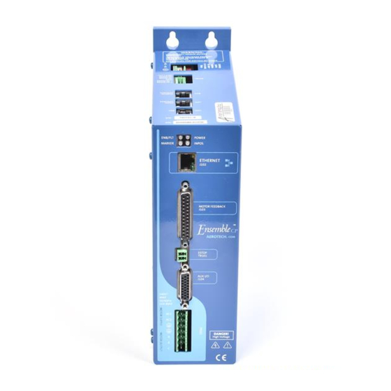
Aerotech Ensemble CP Series Hardware Manual (118 pages)
Brand: Aerotech
|
Category: Computer Hardware
|
Size: 25 MB