Sign In
Upload
Manuals
Brands
AE Techron Manuals
Amplifier
7224
AE Techron 7224 Linear Power Amplifier Manuals
Manuals and User Guides for AE Techron 7224 Linear Power Amplifier. We have
4
AE Techron 7224 Linear Power Amplifier manuals available for free PDF download: Operator's Manual, Step-By-Step Manual, Setup Instructions
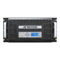
AE Techron 7224 Operator's Manual (49 pages)
Single-Channel Industrial Amplifier for Demanding, High-Power Systems
Brand:
AE Techron
| Category:
Amplifier
| Size: 21 MB
Table of Contents
Declaration of Conformity
3
Table of Contents
4
1 Introduction
6
Features
6
Figure 1.1 - 7224 Front Panel
6
2 Amplifier Setup
7
Safety First
7
Unpacking
7
Installation
7
Connecting the Load
8
Connecting the Input Signal
8
Figure 2.1 - 7224 Back Panel
8
Figure 2.2 - Connecting the Load
8
Figure 2.3 - Closeup of the Output Terminals
8
Figure 2.4 - Closeup of SIM Card
9
Figure 2.5 - Wiring for Unbalanced or Balanced Input Connector
9
Connecting the AC Supply
10
Start-Up Procedure
10
Figure 2.6 - Closeup of AC Mains Outlet
10
Figure 2.7 - Sample of Configurations Setting Label
10
3 Amplifier Operation
11
Front-Panel Controls
11
Figure 3.1 - Power Switch
11
Figure 3.2 - Gain Control
11
Figure 3.3 - Push Buttons
11
Front-Panel Indicators
12
Figure 3.4 - Indicators
12
Figure 3.5 - Main Status Indicators for Stand-Alone Amplifiers
12
Figure 3.6 - Fault Status Indicators for Stand-Alone Amplifiers
13
Figure 3.7 - Main Status Indicators for Multi-Amplifier Systems
14
Figure 3.8 - Fault Status Indicators for Multi-Amplifier Systems
15
Back-Panel Controls and Connectors
17
Figure 3.9 - Back Panel Controls and Connectors
17
4 Advanced Configuration
18
Configuration Access Panel
18
Configuration Settings Located on the Main Board
18
Figure 4.1 - Access Panel Screw Locations
18
Figure 4.2 - Main Board Location Inside Access Panel
19
Figure 4.3 - Master/Slave Setting
19
Figure 4.4 - Gain Trim Control
19
Figure 4.5 - Controlled-Voltage/Controlled-Current Mode Setting
20
Figure 4.6 - Compensation Setting
20
Figure 4.7 - Run Mode/Stop Mode on Power-Up Setting
20
Configuration Settings Located on the Power Supply Board
21
Figure 4.8 - Standby Mode on over Temp Setting
21
Figure 4.9 - Standby Mode on over Load Setting
21
Figure 4.11 - Location of Amplifier High-Voltage Transformer Sockets
22
Figure 4.10 - Accessing the Power Supply Board
22
Figure 4.12 - J3 and J7 Plug Locations for High-Current Output
22
Figure 4.13 - J4 and J8 Plug Locations for High-Voltage Output
22
Figure 4.14 - Bi-Level Power Switch Location
23
5 Applications
24
Remote Status and Control Using the SIM Interlock I/O Connector
24
Figure 5.1 - Remote Status and Control Pinouts
24
Figure 5.2 - Remote Run/Standby Monitor
24
Figure 5.3 - Remote Status and Reset Schematic
25
Figure 5.4 - Remote Enable/Standby
26
Figure 5.5 - Remote Voltage Monitoring
27
Figure 5.6 - Remote Current Monitoring
27
Controlled Current Operation
28
Figure 5.7 - Remote Current Monitoring, Alternate Method
28
Figure 5.8 - Input to Output Comparison, Controlled-Voltage Operation
28
Figure 5.9 - Input to Output Comparison, Controlled-Current Operation
29
Figure 5.10 - Factory-Installed Default RC Network
29
Figure 5.11 - Custom Compensation Location
31
Figure 5.12 - Compensation Effects on Waveform
31
Multi-Amplifier Systems
32
Figure 5.13 - Square Wave Showing a Decrease in R Is Required
32
Figure 5.14 - Square Wave Showing an Increase in R Is Required
32
Figure 5.15 - Square Wave Showing an Increase in C Is Required
32
6 Amplifier Signal Flow
37
Input Signals
37
AC Mains Power
37
Figure 6.1 - Board-Level Functional Block Diagram
37
7 Maintenance
38
Clean Amplifier Filter and Grills
38
8 Troubleshooting
39
Introduction & Precautions
39
Visual Inspection
39
Figure 8.1 - +VCC and -VCC Point Locations
39
No Signal
40
No Leds Illuminated or no Fans
40
Overvoltage LED Lit
40
Standby LED Remains Illuminated
40
Figure 8.2 - Fuse F1 Location
40
Figure 8.3 - Interlock I/O Connector
40
Amplifier Overheats (over Temp Fault Condition)
41
Fault LED Is Illuminated
41
Factory Service
41
9 Specifications
43
Physical Characteristics
44
Figure 9.1 - Voltage Potential Vs. Frequency
45
Figure 9.2 - Frequency Response
45
Figure 9.3 - Noise Vs. Frequency
45
Figure 9.4 - Continuous Power Vs. Frequency
45
Figure 9.5 - Thermal Performance
45
Figure 9.6 - DO 160 Section 18.2 AC Power Processing
45
Figure 9.7 - DC Current over Time at 13.5 VDC
46
Figure 9.8 - DC Current over Time, 2-Ohm Load
46
Figure 9.9 - DC Current over Time 3-Ohm Load
46
Figure 9.10 - DC Current over Time, 4-Ohm Load
46
Figure 9.11 - DC Current over Time Comparison with 4-Ohm Load
46
Advertisement
AE Techron 7224 Operator's Manual (50 pages)
Single-Channel Industrial Amplifiers for Demanding, High-Power Systems
Brand:
AE Techron
| Category:
Amplifier
| Size: 3 MB
Table of Contents
Declaration of Conformity
3
Table of Contents
4
1 Introduction
6
Features
6
Figure 1.1 - 7224 & 7226 Front Panels
6
2 Amplifier Unpacking and Installation
7
Safety First
7
Unpacking
7
Installation
7
3 Connections and Startup
8
Other Operation Modes and Configurations
8
Connecting the Load
8
Figure 3.1 - 7224/7226 Back Panel
8
Connecting the Input Signal
9
Figure 3.2 - Closeup of the Output Terminal Resistor
9
Figure 3.3 - Connecting the Load
9
Figure 3.4 - Closeup of SIM Card
9
Connecting the AC Supply
10
Figure 3.5 - Wiring for Unbalanced or Balanced Input Connector
10
Figure 3.6 - Closeup of AC Mains Outlet
10
Figure 3.7 - Sample of Configurations Setting Label
10
Start-Up Procedure
11
4 Amplifier Operation
12
Front-Panel Controls
12
Figure 4.1 - Power Switch
12
Figure 4.2 - Gain Control
12
Figure 4.3 - Push Buttons
13
Figure 4.4 - Indicators
13
Figure 4.5 - Main Status Indicators
13
Figure 4.6 - Fault Status Indicators
14
Back-Panel Controls and Connectors
15
Figure 4.7 - Back Panel Controls and Connectors
15
5 Advanced Configuration
16
Configuration Access Panel
16
Configuration Settings Located on the Main Board
16
Figure 5.1 - Access Panel Screw Locations
16
Figure 5.2 - Main Board Location Inside Access Panel
17
Figure 5.3 - Master/Slave Setting
17
Figure 5.4 - Gain Trim Control
17
Figure 5.5 - Controlled-Voltage/Controlled-Current Mode Setting
18
Figure 5.6 - Compensation Setting
18
Configuration Settings Located on the Power Supply Board
19
Figure 5.7 - Run Mode/Stop Mode on Power-Up Setting
19
Figure 5.8 - Standby Mode on over Load Setting
19
Figure 5.9 - Accessing the Power Supply Board
20
Figure 5.10 - Location of Amplifier High-Voltage Transformer Sockets
20
Figure 5.11 - J3 and J7 Plug Locations for High-Current Output
20
Figure 5.12 - J4 and J8 Plug Locations for High-Voltage Output
20
Figure 5.13 - Bi-Level Power Switch Location
20
Output Settings
21
6 Applications
22
Remote Status and Control Using the SIM Interlock I/O Connector
22
Figure 6.1 - Remote Status and Control Pinouts
22
Figure 6.2 - Remote Run/Standby Monitor
22
Figure 6.3 - Remote Status and Reset Schematic
23
Figure 6.4 - Remote Enable/Standby
24
Figure 6.5 - Remote Current Monitoring
25
Figure 6.6 - Remote Current Monitoring, Alternate Method
25
Controlled Current Operation
26
Figure 6.7 - Input to Output Comparison, Controlled-Voltage Operation
26
Figure 6.8 - Input to Output Comparison, Controlled-Current Operation
26
Figure 6.9 - Factory-Installed Default RC Network
27
Figure 6.10 - Custom Compensation Location
29
Figure 6.11 - Compensation Effects on Waveform
29
Figure 6.12 - Square Wave Showing a Decrease in R Is Required
29
Figure 6.13 - Square Wave Showing an Increase in R Is Required
29
Figure 6.14 - Square Wave Showing a Decrease in C Is Required
29
Multi-Amplifier Systems
30
Accessory Recommendations by System Type
31
Figure 6.15 - Main Status Indicators for Multi-Amplifier Systems
32
Figure 6.16 - Fault Status Indicators for Multi-Amplifier Systems
33
7 Amplifier Signal Flow
38
Input Signals
38
AC Mains Power
38
Figure 7.1 - Board-Level Functional Block Diagram
38
8 Maintenance
39
Clean Amplifier Filter and Grills
39
9 Troubleshooting
40
Introduction & Precautions
40
Visual Inspection
40
Figure 9.1 - +VCC and -VCC Point Locations
40
No Signal
41
No Leds Illuminated or no Fans
41
Overvoltage LED Lit
41
Standby LED Remains Illuminated
41
Figure 9.2 - Fuse F1 Location
41
Figure 9.3 - Interlock I/O Connector
41
Amplifier Overheats (over Temp Fault Condition)
42
Fault LED Is Illuminated
42
Factory Service
42
10 Specifications
44
Figure 10.1 - 7224 Voltage Potential Vs. Frequency
46
Figure 10.2 - 7226 Voltage Potential Vs. Frequency
46
Figure 10.3 - 7224 & 7226 Frequency Response
46
Figure 10.4 - 7224 Noise Vs. Frequency
46
Figure 10.5 - 7224 Continuous Power Vs. Frequency
46
Figure 10.6 - 7224 Thermal Performance
46
Figure 10.7 - 7224 DC Current over Timeat 13.5 VDC
47
Figure 10.8 - 7224 DC Current over Timecomparison with 4-Ohm Load
47
Figure 10.9 - 7224 DO 160 Section 18.2 AC Power Processing
47
AE Techron 7224 Step-By-Step Manual (32 pages)
multi-amp system
Brand:
AE Techron
| Category:
Amplifier
| Size: 1 MB
Table of Contents
Table of Contents
2
1 Multi-Amp Systems Using 2100 or 7000 Series Amplifiers
4
Safety First
4
Overview
4
Multi-Amp Configuration Accessories
4
Figure 1.1 - Maximum Continuous Output in 7000-Series Multi-Amp Systems
4
Accessory Recommendations by System Type
5
2 Multi-Amp System Principles
6
One Master Amplifier for Series Systems
6
All Master Amplifiers for Parallel Systems
6
Use Only 7000-Series Amplifiers of the same Model Number
6
Use Correct Wiring
6
When Constructing Output Wiring, Use These Basic Criteria
6
Operate with Safety in Mind
6
3 Series Systems Configuration and Wiring
7
Choosing Single-Ended or Differential Configuration for Two-Amplifier Systems
7
Configure SIM-BNC-OPTOC Input Cards
7
Figure 3.1 - Two in Series: Single-Ended Vs. Differential
7
Figure 3.2 - SIM-BNC-OPTOC Card Jumper Locations
7
Install SIM-BNC-OPTOC Input Cards in Amplifiers
8
Configure Amplifiers' Main Boards for Slave Operation
8
Remove Output Terminal Resistor
9
Attach Master/Slave Labels (Optional)
9
Figure 3.3 - 7224 Amplifier Access Panel Screw Locations
9
Figure 3.4 - Master/Slave Jumper Locations
9
Figure 3.5 - 7224 Output Terminal Resistor
9
Figure 3.6 - 7548/7796 Output Terminal Resistor
9
Series System Wiring
10
Two in Series - Differential
10
Figure 3.7 - Terminating the Amplifier Input
10
Figure 3.8 - Verifying DC Offset
11
Figure 3.9 - Verifying Amp Gain
11
Figure 3.10 - Verifying System Gain
12
Figure 3.11 - Two Amplifiers in Series - Differential Configuration
12
Two or Three in Series - Single Ended
13
Figure 3.12 - Terminating the Amplifier Input
13
Figure 3.14 - Verifying Amp Gain
14
Figure 3.13 - Verifying DC Offset
14
Figure 3.15 - Verifying System Gain
15
Figure 3.16 - Two Amplifiers in Series - Single-Ended Configuration
15
Figure 3.17 - Three Amplifiers in Series - Single-Ended Configuration
16
4 Parallel Systems Configuration, Wiring and Balancing
17
Install Ballast Resistors
17
Figure 4.1 - 7224 Ballast Resistor Mounting
17
Figure 4.2 - 7796 Ballast Resistor Mounting
17
Figure 4.3 - 7224 Ballast Resistor Connected to Output Terminal
17
Figure 4.4 - 7796 Ballast Resistors Connected to Output Terminal
17
Main Board Access
18
Disable Gain Controls (7224 Amplifiers Only)
18
Figure 4.5 - Access Panel Screw Locations
18
Figure 4.6 - Gain Control Connection on Main Board
18
Parallel System Balancing
19
Connect for Balancing
19
Figure 4.7 - Gain Control Pin Settings
19
Figure 4.8 - Connecting for Balancing (Four in Parallel Shown)
19
Verify Interlock Operation
20
Adjust DC Offset
20
Wire and Connect Parallel Inputs
20
Figure 4.9 - Terminating the Amplifier Input
20
Figure 4.10 - Main Board Balancing Control Locations
20
Verify and Adjust Amplifier Gain
21
Figure 4.11 - Wiring and Test Points for DC Offset
21
Figure 4.12 - Wiring the Paralleled Input Wire
21
Figure 4.13 - Optional BNC Parallel Input Wiring (Three in Parallel Shown)
21
Amplifier Gain Matching
22
Figure 4.14- Wiring and Test Points for Amp Gain
22
Figure 4.15- Wiring and Test Points for Gain Matching
23
Verify Minimal Circulating Currents
24
Verify Current Sharing
24
Figure 4.16 - Two Amplifiers Paralleled
24
Figure 4.17 - Three Amplifiers Paralleled
25
Figure 4.18 - Four Amplifiers Paralleled
26
Appendix A Wire Current-Carrying Capacity
27
Figure A-1 - Wire Current-Carrying Capacity Chart
27
Appendix B Critical Wire Lengths in Parallel Systems
28
Figure B-1 - Critical Wire Lengths in Parallel Systems
28
Appendix C Building Parallel System Output Cables
29
Figure C-1 - Output Cables Constructed for Use in a Two-In-Parallel System
29
Appendix D Building the DB-25 Interlock Cable
30
Figure D-1 - DB-25 Cable Wiring for a Four-In-Parallel System
30
Appendix E Returning Slave Amplifiers to Stand-Alone Use
31
Figure E-1 - 7224 Access Panel Screw Locations
31
Figure E-2 - Master/Slave Jumper Locations
31
Figure E-3 - Output Terminal Resistor
31
Figure E-4 - 7548/7796 Output Terminal Resistor
31
Figure E-5 - SIM-BNC-OPTOC, Factory Default Settings
32
Advertisement
AE Techron 7224 Setup Instructions (5 pages)
Parallel Amplifier System
Brand:
AE Techron
| Category:
Amplifier
| Size: 0 MB
Table of Contents
Table of Contents
2
Table of Contents
3
Introduction
3
Special High-Frequency Applications
3
Parallel Operation
3
Figure 2.1 - Circulating Ground Current Bleed Resistor
3
Access the Main Board
4
Master/Slave Settings
4
Remove Output Cables
4
Verify CV Setting
4
Enable Amplifiers
5
Measure Current
5
Measure Voltage
5
Power down
5
Reconnect
5
Figure 2.5 - Slave Gain Trim
5
Figure 2.4 - CC / CV Setting
5
Figure 2.3 - Master / Slave Setting
5
Figure 2.6 - IMON Current Monitor
5
Advertisement
Related Products
AE Techron 7212
AE Techron 7226
AE Techron 7000-Series
AE Techron 7000 Series
AE Techron 7796HC
AE Techron 7810-100-100
AE Techron 7810-200-50
AE Techron 7815-100-150
AE Techron 7815-300-50
AE Techron 7820-100-200
AE Techron Categories
Amplifier
Portable Generator
Transformer
Inverter
More AE Techron Manuals
Login
Sign In
OR
Sign in with Facebook
Sign in with Google
Upload manual
Upload from disk
Upload from URL