Sign In
Upload
Manuals
Brands
Advantech Manuals
Computer Hardware
PCE-5124
Advantech PCE-5124 Manuals
Manuals and User Guides for Advantech PCE-5124. We have
1
Advantech PCE-5124 manual available for free PDF download: User Manual
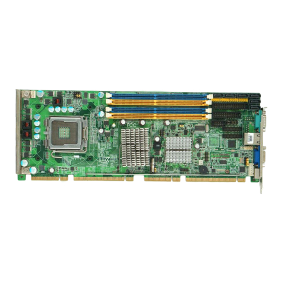
Advantech PCE-5124 User Manual (138 pages)
LGA775 Intel Core 2 Quad / Core 2 Duo Processor-based 800/1066/1333 MHz FSB PICMG 1.3 Single Host Board with PCIe / DDR2 / Dual GbE LAN
Brand:
Advantech
| Category:
Computer Hardware
| Size: 5 MB
Table of Contents
User Manual
1
Table of Contents
9
Chapter 1 Hardware Configuration
16
Introduction
16
Features & Benifits
17
Specifications
18
System
18
Memory
18
Input/Output
19
Graphics
19
Ethernet LAN
19
Industrial Features
19
Mechanical and Environmental Specifications
20
Jumpers and Connectors
20
Table 1.1:Jumper List
20
Table 1.2:Connector List
21
Board Layout: Jumper and Connector Locations
23
Figure 1.1:Jumper and Connector Locations
23
PCE-5124 Block Diagram
24
Figure 1.2:PCE-5124 Block Diagram
24
Safety Precautions
25
Jumper Settings
26
How to Set Jumpers
26
CMOS Clear (CMOS1)
26
Table 1.3:CMOS (CMOS1)
26
Watchdog Timer Output (JWDT1)
28
Table 1.4:Watchdog Timer Output (JWDT1)
28
COM2 RS-232/422/485 Mode Selector (JESTCOM2)
30
Figure 1.3: COM2 RS-232/422/485 Jumper Setting
30
Table 1.6:COM2 RS-232/422/485 Mode Selector
30
Table 1.5: H/W Monitor Alarm (JOBS1)
30
System Memory
32
Memory Installation Procedures
33
Cache Memory
33
Processor Installation
33
Chapter 2 Connecting Peripherals
36
Introduction
36
Floppy Drive Connector (FDD1)
37
Parallel Port (LPT1)
38
USB Ports (USB12, USB34, USB56, USB78)
39
VGA Connector (VGA1)
40
Serial Ports (COM1, COM2, COM3-4 & COM5-6)
41
PS/2 Keyboard and Mouse Connector (KBMS1)
43
CPU Fan Connector (CPUFAN1)
44
Front Panel Connectors (JFP1, JFP2 & JFP3)
45
Power LED and Keyboard Lock (JFP3)
45
Table 2.1:PS/2 or ATX Power Supply LED Status
46
External Speaker (JFP2)
46
Reset Connector (JFP1)
46
HDD LED Connector (JFP2)
46
ATX Soft Power Switch (JFP1)
46
H/W Monitor Alarm (JOBS1)
47
LAN Ports (LAN1 & LAN2)
48
Table 2.2:LAN LED Indicator
48
High Definition Audio Module Interface
49
GPIO Header (GPIO1)
50
Case Open Connector (JCASE1)
51
Front Panel LAN Indicator Connector (LANLED1)
52
Table 2.3:Front Panel LAN Indicator Connector
52
Serial ATA Interface (SATA1~SATA6)
53
Figure 3.1:Setup Program Initial Screen
56
Chapter 3 AMI BIOS Setup
56
Entering Setup
57
Figure 3.2:Press del to Run Setup
57
Main Setup
58
Figure 3.3:Main Setup Screen
58
System Time / System Date
58
Advanced BIOS Features Setup
59
Figure 3.4:Advanced BIOS Features Setup Screen
59
CPU Configuration
60
Figure 3.5:CPU Configuration Setting
60
IDE Configuration
62
Figure 3.6:IDE Configuration
62
Super I/O Configuration
63
Figure 3.7:Super I/O Configuration
63
Hardware Health Function
65
Figure 3.8:Hardware Health Configuration
65
APM Configuration
66
Figure 3.9:APM Configuration
66
PCI/PNP Setup
68
Clear NVRAM
68
Figure 3.11:PCI/PNP Setup
68
Plug and Play O/S
68
Allocate IRQ to PCI VGA
69
Irq
69
Off Board PCI/ISA IDE Card
69
Palette Snooping
69
PCI IDE Busmaster
69
PCI Latency Timer
69
Boot Setup Utility
70
Figure 3.12:Boot Setup Utility
70
Figure 3.13:Boot Setting Configuration
71
Figure 3.14:Password Configuration
72
Security Setup
72
Advanced Chipset Settings
73
Figure 3.15:Advanced Chipset Settings
73
Figure 3.16:North Bridge Configuration
74
Figure 3.17:Video Function Configuration
75
Figure 3.18:South Bridge Configuration
76
Exit Option
77
Figure 3.19:Exit Option
77
Save Changes and Exit
77
Discard Changes and Exit
78
Load Fail-Safe Defaults
78
Load Optimal Defaults
78
Chapter 4 Chipset Software Install Utility
80
Before You Begin
80
Introduction
80
Windows XP Driver Setup
81
Chapter 5 VGA Setup
86
Introduction
86
Windows XP Driver Setup
86
Chapter 6 Onboard Security Setup
92
Introduction
92
Windows XP Driver Setup
92
Using the OBS Hardware Doctor Utility
94
Chapter 7 LAN Configuration
98
Introduction
98
Features
98
Installation
98
Win XP Driver Setup (LAN)
99
Chapter 8 SATA RAID Setup
104
Introduction
104
SATA RAID Driver and Utility Setup
104
A.1 Introduction
106
A.1.1 Watchdog Timer Overview
106
Appendix A Programming the Watchdog Timer
106
Table A.1:Watchdog Timer Registers
108
A.1.3 Example Program
109
Appendix B I/O Pin Assignments
116
B.1 Floppy Drive Connector (FDD1)
116
Table B.1:Floppy Drive Connector (FDD1)
116
B.2 Parallel Port Connector (LPT1)
117
Table B.2:Parallel Port Connector (LPT1)
117
B.3 VGA Connector (VGA1)
118
Table B.3:VGA Connector (VGA1)
118
B.4 RS-232 Serial Port (COM1)
119
Table B.4:RS-232 Serial Port (COM1)
119
B.5 RS 232/422/485 Serial Port (COM2)
120
Table B.5:RS-232 / 422 / 485 Serial Port (COM2)
120
B.6 RS-232 Serial Port (COM3-4)
121
Table B.6:RS-232 Serial Port (COM3-4)
121
B.7 RS-232 Serial Port (COM5-6)
122
Table B.7:RS-232 Serial Port (COM5-6)
122
B.8 USB Header (USB12 ~ 78)
123
B.9 PS/2 Keyboard/Mouse Connector (KBMS1)
123
Table B.8:USB Header (USB12 ~ 78)
123
B.10 External Keyboard Connector (KBMS2)
124
B.11 CPU Fan Power Connector (CPUFAN1)
124
Table B.10:External Keyboard Connector (KBMS2)
124
Table B.11: CPU Fan Power Connector (CPUFAN1)
124
B.12 Power LED and Keyboard Lock Connector (JFP3 PWR_LED & KEY LOCK)
125
B.13 External Speaker Connector (JFP2 / SPEAKER)
125
Table B.12:Power LED and Keyboard Lock Connector
125
Table B.13:External Speaker Connector (JFP2 / SPEAK
125
B.14 Reset Connector (JFP1 / RESET)
126
B.15 Hdd Led (Jfp2 / Hddled)
126
Table B.14:Reset Connector (JFP1 / RESET)
126
Table B.15:HDD LED (JFP2 / HDDLED)
126
B.16 ATX Soft Power Switch (JFP1 / PWR_SW)
127
B.17 Hi-Definition Audio Link Connector (HDAUD1)
127
B.18 SM Bus Connector (JFP2 / SNMP)
128
Table B.18:SM Bus Connector (JFP2 / SNMP)
128
B.19 LAN1 and LAN2 LED Connector (LANLED1)
128
B.20 GPIO Header (GPIO1)
129
Table B.20:GPIO Header (GPIO1)
129
B.21 System I/O Ports
130
Table B.21:System I/O Ports
130
B.22 DMA Channel Assignments
131
Table B.22:DMA Channel Assignments
131
B.23 Interrupt Assignments
132
Table B.23:Interrupt Assignments
132
B.24 1St MB Memory Map
132
Table B.24:1St MB Memory Map
132
B.25 PCI Bus Map
133
Table B.25:PCI Bus Map
133
C.1 Supported GPIO Register
136
C.1.1 GPIO Registers
136
Appendix C Programming GPIO
136
C.1.2 GPIO Example Program-1
137
Advertisement
Advertisement
Related Products
Advantech PCE-7214
Advantech PCE-5B12-07
Advantech PCE-7B13-07
Advantech PCE-5130
Advantech PCE-5133
Advantech PCE-5033
Advantech PCE-2033
Advantech PCE-2133
Advantech PCM-26R1EC
Advantech PCL-847A
Advantech Categories
Motherboard
Computer Hardware
Desktop
Network Router
Touch Panel
More Advantech Manuals
Login
Sign In
OR
Sign in with Facebook
Sign in with Google
Upload manual
Upload from disk
Upload from URL