Sign In
Upload
Manuals
Brands
Advantech Manuals
PCI Card
PCA-6008G2
Advantech PCA-6008G2 Manuals
Manuals and User Guides for Advantech PCA-6008G2. We have
1
Advantech PCA-6008G2 manual available for free PDF download: User Manual
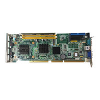
Advantech PCA-6008G2 User Manual (104 pages)
Socket 479 Pentium© M/ Celeron© M Processor Card with VGA/ Dual Gigabit LAN/ HISA/ DVI (533/400 MHz FSB)
Brand:
Advantech
| Category:
PCI Card
| Size: 4.17 MB
Table of Contents
Table of Contents
9
Chapter 1 Hardware Configuration
15
Introduction
16
Features
16
Specifications
17
System
17
Memory
17
Input/Output
17
VGA Interface
17
Ethernet LAN
18
Industrial Features
18
Mechanical and Environmental Specifications
18
Jumpers and Connectors
18
Board Layout: Jumper and Connector Locations
20
PCA-6008 Block Diagram
21
Safety Precautions
21
Jumper Settings
22
How to Set Jumpers
22
CMOS Clear (CMOS1)
22
Watchdog Timer Output (JWDT1)
22
JSETCOM2 (RS232/422/485 Jumper Setting (JSETCOM2))
23
System Memory
23
CPU FSB and Memory Speed
24
Dual Channel Configuration
24
Memory Installation Procedures
24
Processor Installation
24
Chapter 2 Connecting Peripherals
25
Introduction
26
1St (IDE1) IDE Connector
26
Floppy Drive Connector (FDD1)
26
Parallel Port (LPT1)
27
USB Ports (USB12, USB34, USB56, USB78)
28
VGA Connector (VGA1)
28
DVI Connector (DVI1)
29
Ethernet Connector (LAN1, LAN2)
29
Serial Ports (COM1, COM2, COM3, COM4, COM5, COM6 )
30
PS/2 Keyboard/Mouse Connector (KBMS1)
30
External Keyboard Connector (KBMS2)
31
CPU Fan Connector (CPUFAN1)
31
Front Panel Connectors (JFP1, JFP2, JFP3)
31
ATX Soft Power Switch (JFP1 / PWR_SW)
32
Reset (JFP1 / RESET)
32
Hdd Led (Jfp2 / Hddled)
32
SM Bus Connector (JFP2 / SNMP)
32
External Speaker (JFP2 / SPEAKER)
32
Power LED and Keyboard Lock Connector (JFP3 / PWR_LED&KEY LOCK)
32
ATX Feature Connector (JATXF1)
33
Audio Interface (AC-97)
33
Serial ATA Interface (SATA1, SATA2)
34
Auxiliary 4-Pin Power Connector (ATX12V1)
34
Hardware Monitor Alarm (JWDT1+JOBS1+JIR1)
34
Case Open Connector (JCASE1)
35
LAN1 and LAN2 LED (LANLED1)
36
GPIO Pin Header (GPI01)
36
LVDS Connector (LVDS1)
36
LVDS Jumper (JLVDS1)
37
LVDS Invert (VP1)
37
Chapter 3 Award BIOS Setup
39
Introduction
40
CMOS RAM Auto-Backup and Restore
40
Entering Setup
40
Standard CMOS Setup
41
Date
41
The Date Format Is <Week>, <Month>, <Day>, <Year
41
Time
41
IDE Channel 0/1 Master/Slave
41
Drive a / Drive B
41
Halt on
42
Memory
42
Advanced BIOS Features
42
CPU Features
42
Hard Disk Boot Priority
43
Virus Warning
43
CPU L1 & L2 Cache
43
Quick Power on Self Test
43
First/Second/Third Boot Device
43
Boot Other Device
43
Swap Floppy Drive
43
Boot up Floppy Seek
43
Boot up Numlock Status
43
Gate A20 Option
43
Typematic Delay (Msec)
44
Security Option
44
APIC Mode
44
MPS Version Control for os
44
Advanced Chipset Features
45
DRAM Timing Selectable
45
CAS Latency Time
45
DRAM RAS# to CAS# Delay
45
DRAM RAS# Precharge
45
Precharge Delay (T RAS)
46
System Memory Frequency
46
System BIOS Cacheable
46
Video BIOS Cacheable
46
PC Health Status
55
Case Open Warning
55
CPU Warning Temperature
55
Current CPU Temperature
55
CPU FAN Speed
55
VCORE and Other Voltages
55
Shutdown Temperature
55
Frequency / Voltage Control
56
Spread Spectrum
56
Password Setting
56
Save & Exit Setup
57
Exit Without Saving
57
Chapter 4 Chipset Software Install Utility
59
Before You Begin
60
Introduction
60
Windows XP Driver Setup
60
Chapter 5 VGA Setup
65
Introduction
66
Windows XP Driver Setup
66
Chapter 6 LAN Configuration
69
Introduction
70
Features
70
Installation
70
Win XP Driver Setup (Realtek RTL8111B)
71
Chapter 7 USB 2.0 Configuration
73
Introduction
74
Features
74
Installation
74
Appendix A Programming the Watchdog
75
Programming the Watchdog Timer
76
Appendix B Programming the GPIO
83
Sample Code
84
Appendix C Pin Assignments
87
IDE Hard Drive Connector (IDE1)
88
Floppy Drive Connector (FDD1)
89
Parallel Port Connector (LPT1)
90
USB Connector (USB12, USB34, USB56, USB78)
90
VGA Connector (VGA1)
91
DVI Connector(DVI1)
92
Serial Port (COM1, COM2)
92
PS/2 Keyboard/ Mouse Connnector (KBMS1)
93
External Keyboard Connector (KBMS2)
93
CPU Fan Power Connector (CPUFAN1)
94
Power LED & Keyboard Lock Connector (JFP2)
94
External Speaker Connector (JFP2/ SPEAKER)
94
Reset Connector (JFP1/ RESET)
95
HDD LED Connector (JFP2/ HDDLED)
95
ATX Feature Connector (JATXF1)
95
ATX Soft Power Switch (JFP1/ PWR_SW))
96
H/W Monitor Alarm (JOBS1)
96
Audio Interface (AC-97)
96
SM Bus Connector (JFP2/ SNMP)
97
Case Open Connector (JCASE)
97
LAN1 and LAN2 Connector (LANLED1)
97
GPIO Pin Header (GPIO1)
98
LVDS Connector (LVDS1)
98
LVDS Power Jumper (JLVDS1)
99
LVDS Invert (VP1)
100
System I/O Ports
101
DMA Channel Assignments
101
Interrupt Assignments
102
1St MB Memory Map
102
PCI Bus Map
102
Advertisement
Advertisement
Related Products
Advantech PCA-684
Advantech PCA-6184
Advantech PCA-6005-B
Advantech PCA-6008VG
Advantech PCA-6194
Advantech PCA-6184VE
Advantech PCI-1723
Advantech PCI-1710L
Advantech PCI-1610AUP
Advantech PCLS-848-P
Advantech Categories
Motherboard
Computer Hardware
Desktop
Network Router
Touch Panel
More Advantech Manuals
Login
Sign In
OR
Sign in with Facebook
Sign in with Google
Upload manual
Upload from disk
Upload from URL