Sign In
Upload
Manuals
Brands
Advantech Manuals
PCI Card
PCA-6008VG
Advantech PCA-6008VG Manuals
Manuals and User Guides for Advantech PCA-6008VG. We have
1
Advantech PCA-6008VG manual available for free PDF download: User Manual
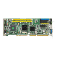
Advantech PCA-6008VG User Manual (96 pages)
Celeron M Processor Card with VGA/ Single Gigabit LAN/ HISA/ (400 MHz FSB)
Brand:
Advantech
| Category:
PCI Card
| Size: 5.35 MB
Table of Contents
Declaration of Conformity
3
Safety Instructions
5
Table of Contents
9
Chapter 1 Hardware Configuration
15
Introduction
16
Features
16
Specifications
17
System
17
Memory
17
Input/Output
17
VGA Interface
17
Ethernet LAN
17
Industrial Features
18
Mechanical and Environmental Specifications
18
Jumpers and Connectors
18
Table 1.1: Jumpers
19
Board Layout: Jumper and Connector Locations
20
PCA-6008 Block Diagram
21
Safety Precautions
21
Jumper Settings
22
CMOS Clear (CMOS1)
22
How to Set Jumpers
22
Watchdog Timer Output (JWDT1)
22
JSETCOM2 (RS232/422/485 Jumper Setting (JSETCOM2))
23
Table 1.4: Watchdog Timer Output (JWDT1)
23
System Memory
23
CPU FSB and Memory Speed
24
Dual Channel Configuration
24
Memory Installation Procedures
24
Processor Installation
24
Chapter 2 Connecting Peripherals
25
Introduction
26
1St (IDE1) IDE Connector
26
Floppy Drive Connector (FDD1)
26
Parallel Port (LPT1)
27
USB Ports (USB12, USB34)
28
VGA Connector (VGA1)
28
Ethernet Connector (LAN1)
29
Serial Ports (COM1, COM2)
29
PS/2 Keyboard/Mouse Connector (KBMS1)
30
External Keyboard Connector (KBMS2)
30
CPU Fan Connector (CPUFAN1)
31
Front Panel Connectors (JFP1, JFP2, JFP3)
31
ATX Soft Power Switch (JFP1 / PWR_SW)
31
Reset (JFP1 / RESET)
32
Hdd Led (Jfp2 / Hddled)
32
SM Bus Connector (JFP2 / SNMP)
32
External Speaker (JFP2 / SPEAKER)
32
Power LED and Keyboard Lock Connector (JFP3 / PWR_LED&KEY LOCK)
32
ATX Feature Connector (JATXF1)
33
Audio Interface (AC-97)
33
Ac-97 Audio Interface (Ac)
33
Serial ATA Interface (SATA1, SATA2)
33
Auxiliary 4-Pin Power Connector (ATX12V1)
34
Hardware Monitor Alarm (JWDT1+JOBS1+JIR1)
34
Case Open Connector (JCASE1)
35
Lan1Led (Lanled1)
35
GPIO Pin Header (GPI01)
36
Chapter 3 Award BIOS Setup
37
Introduction
38
CMOS RAM Auto-Backup and Restore
38
Entering Setup
38
Standard CMOS Setup
39
Date
39
The Date Format Is <Week>, <Month>, <Day>, <Year
39
Time
39
IDE Channel 0/1 Master/Slave
39
Drive a / Drive B
39
Halt on
40
Memory
40
Advanced BIOS Features
40
CPU Features
40
Hard Disk Boot Priority
41
Virus Warning
41
CPU L1 & L2 Cache
41
Quick Power on Self Test
41
First/Second/Third Boot Device
41
Boot Other Device
41
Swap Floppy Drive
41
Boot up Floppy Seek
41
Boot up Numlock Status
41
Gate A20 Option
41
Typematic Delay (Msec)
42
Security Option
42
APIC Mode
42
MPS Version Control for os
42
Advanced Chipset Features
43
DRAM Timing Selectable
43
CAS Latency Time
43
DRAM RAS# to CAS# Delay
43
DRAM RAS# Precharge
43
Precharge Delay (T RAS)
44
System Memory Frequency
44
System BIOS Cacheable
44
Video BIOS Cacheable
44
Memory Hole at 15M-16M
44
PCI-Express Root Port Func
44
On-Chip Frame Buffer Size
44
DVMT Mode
44
Dvmt/ Fixed Memory Size
44
Boot Display
45
Init Display First
45
Integrated Peripherals
45
Ide Dma Transfer Access
46
IDE HDD Block Mode
46
On-Chip Ide Device
46
On-Chip Serial Ata
46
Usb 2.0 Controller
46
Usb Controller
46
Ac-97 Audio
47
Onboard Fdc Controller
47
Onboard Lan1 Control
47
Onboard Serial Port
47
Rxd, Txd Active
47
Uart Mode Select
47
USB Keyboard/Mouse Support
47
Ecp Mode Use Dma
48
Epp Mode Select
48
IR Transmission Delay
48
Onboard Parallel Port
48
Parallel Port Mode
48
Ur2 Duplex Mode
48
Use Ir Pins
48
Power Management Setup
49
Acpi Function
49
Pci Express Pm Function
49
Power Supply Type
49
Hdd Power down
50
Modem Use Irq
50
Poweron by Lan
50
Poweron by Modem
50
Soft-Off by Pwr-Bttn
50
Suspend Mode
50
Suspend Type
50
Table 3.1: D Power down = 15 Min
50
Video off in Suspend
50
Video off Method
50
Poweron by Alarm
51
Primary Ide
51
Pnp/Pci Configurations
51
Pci/Vga Palette Snoop
51
Pnp os Installed
51
Reset Configuration Data
51
Resources Controlled by
51
CPU FAN Speed
52
Maximum Payload Size
52
Shutdown Temperature
52
VCORE and Other Voltages
52
Pc Health Status
52
Case Open Warning
52
Cpu Warning Temperature
52
Current Cpu Temperature
52
Frequency / Voltage Control
53
Spread Spectrum
53
Password Setting
53
Save & Exit Setup
54
Exit Without Saving
54
Chapter 4 Chipset Software Install Utility
55
Before You Begin
56
Introduction
56
Windows XP Driver Setup
56
Chapter 5 VGA Setup
61
Introduction
62
Windows XP Driver Setup
62
Chapter 6 LAN Configuration
65
Introduction
66
Features
66
Installation
66
Win XP Driver Setup (Realtek RTL8111B)
67
Chapter 7 USB 2.0 Configuration
69
Introduction
70
Features
70
Installation
70
Appendix A Programming the Watchdog
71
Programming the Watchdog Timer
72
Table A.1: Watchdog Timer Registers
74
Appendix B Programming the GPIO
79
Sample Code
80
Appendix C Pin Assignments
83
IDE Hard Drive Connector (IDE1)
84
Floppy Drive Connector (FDD1)
85
Parallel Port Connector (LPT1)
86
USB Connector (USB12, USB34)
86
VGA Connector (VGA1)
87
RS-232 Serial Port (COM1, COM2)
88
PS/2 Keyboard/ Mouse Connnector (KBMS1)
88
External Keyboard Connector (KBMS2)
88
CPU Fan Power Connector (CPUFAN1)
89
Power LED & Keyboard Lock Connector (JFP2)
89
Table C.8: External Keyboard Connector (KBMS2)
89
External Speaker Connector (JFP2/ SPEAKER)
90
Reset Connector (JFP1/ RESET)
90
HDD LED Connector (JFP2/ HDDLED)
90
ATX Feature Connector (JATXF1)
90
ATX Soft Power Switch (JFP1/ PWR_SW))
91
H/W Monitor Alarm (JOBS1)
91
Audio Interface (AC-97)
91
SM Bus Connector (JFP2/ SNMP)
92
Case Open Connector (JCASE)
92
LAN1 and LAN2 Connector (LANLED1)
92
GPIO Pin Header (GPIO1)
93
System I/O Ports
94
DMA Channel Assignments
94
C.22 System I/O Ports
94
Interrupt Assignments
95
1St MB Memory Map
95
PCI Bus Map
95
C.24 Interrupt Assignments
95
Advertisement
Advertisement
Related Products
Advantech PCA-684
Advantech PCA-6184
Advantech PCA-6005-B
Advantech PCA-6194
Advantech PCA-6008G2
Advantech PCA-6184VE
Advantech PCI-1625U
Advantech PCI-1710U
Advantech PCI-1706U
Advantech PCIE-1760
Advantech Categories
Motherboard
Computer Hardware
Desktop
Network Router
Touch Panel
More Advantech Manuals
Login
Sign In
OR
Sign in with Facebook
Sign in with Google
Upload manual
Upload from disk
Upload from URL